Arduino Nano-Controlled Servo with I2C LCD Display and Membrane Keypad Interface
Circuit Documentation
Summary
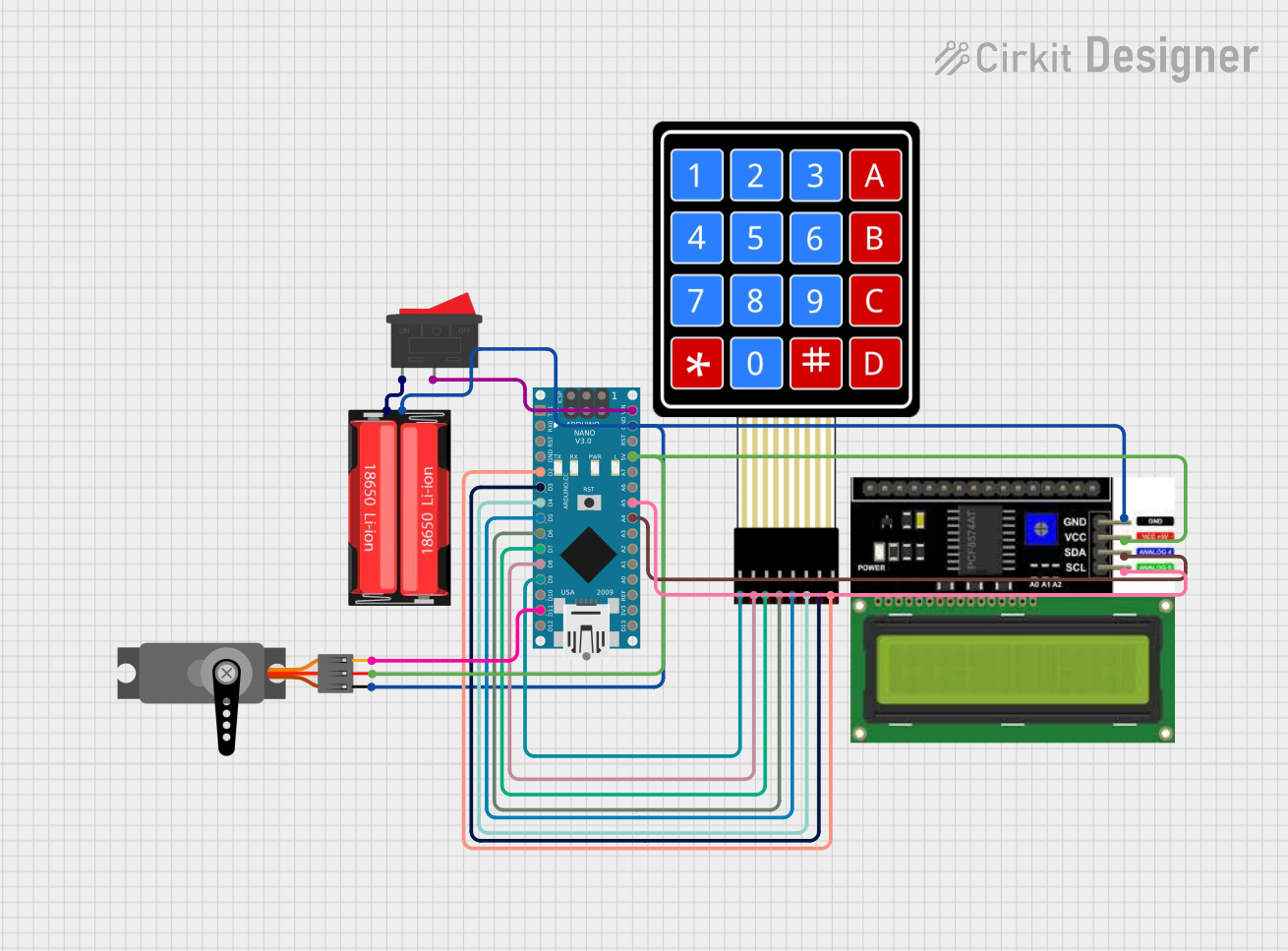
This circuit integrates various components controlled by an Arduino Nano microcontroller. It includes a 4x4 membrane matrix keypad for user input, a servo motor for actuation, an LCD I2C display for output, and a 18650 Li-Ion battery for power supply, with a rocker switch for power control. The Arduino Nano serves as the central processing unit, interfacing with the keypad, servo, and display, while also managing power distribution from the battery.
Component List
Arduino Nano
- Microcontroller board based on the ATmega328P
- Offers a variety of digital and analog I/O pins
- Can be powered via USB or an external power source
18650 Li-Ion Battery
- Rechargeable battery providing a nominal voltage typically around 3.7V
- Used as the power source for the circuit
Rocker Switch
- A simple on-off switch to control the power flow from the battery to the circuit
4X4 Membrane Matrix Keypad
- A 16-button keypad providing user input capability
- Each button press connects one row to one column, which can be detected by the microcontroller
Servo
- An actuator capable of precise position control
- Controlled by PWM signals from the microcontroller
LCD I2C Display
- A display module with I2C communication interface
- Used for displaying information to the user
Wiring Details
Arduino Nano
- D2-D9: Connected to the columns and rows of the 4X4 Membrane Matrix Keypad
- D11/MOSI: Connected to the PWM pin of the Servo
- VIN: Connected to the Rocker Switch for power input
- GND: Common ground with the Servo, LCD I2C Display, and 18650 Li-Ion Battery
- 5V: Power output to the Servo and LCD I2C Display
- A4 (SDA), A5 (SCL): I2C communication lines connected to the LCD I2C Display
18650 Li-Ion Battery
- Positive: Connected to one terminal of the Rocker Switch
- Negative: Common ground with the Servo, Arduino Nano, and LCD I2C Display
Rocker Switch
- Terminal 1: Connected to the positive terminal of the 18650 Li-Ion Battery
- Terminal 2: Connected to the VIN pin of the Arduino Nano
4X4 Membrane Matrix Keypad
- R1-R4: Connected to pins D9-D6 of the Arduino Nano
- C1-C4: Connected to pins D5-D2 of the Arduino Nano
Servo
- PWM: Connected to pin D11/MOSI of the Arduino Nano
- VCC: Power input from the 5V pin of the Arduino Nano
- GND: Common ground with the Arduino Nano
LCD I2C Display
- SDA: Connected to pin A4 of the Arduino Nano
- SCL: Connected to pin A5 of the Arduino Nano
- VCC: Power input from the 5V pin of the Arduino Nano
- GND: Common ground with the Arduino Nano
Documented Code
void setup() {
  // put your setup code here, to run once:

}

void loop() {
  // put your main code here, to run repeatedly:

}
The provided code is a template for the Arduino Nano with empty setup() and loop() functions. The setup() function is intended for initialization code that runs once when the microcontroller is powered on or reset. The loop() function contains the main logic of the program, which runs repeatedly as long as the microcontroller is powered. Additional code is required to handle the keypad input, control the servo, and update the display.