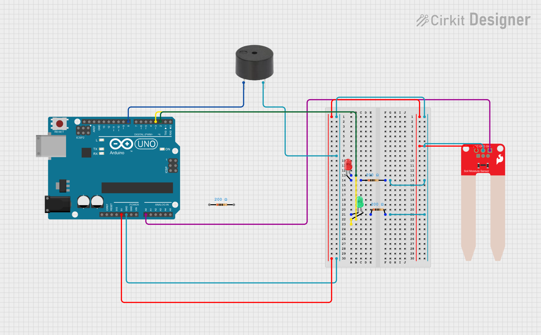
Arduino-Based Soil Moisture Monitoring System with Alert Indicators

Circuit Documentation
Summary of the Circuit
This circuit is designed to monitor soil moisture levels using a SparkFun Soil Moisture Sensor and provide visual and auditory feedback based on the moisture level. An Arduino UNO serves as the central microcontroller unit to process the sensor data. If the soil moisture level is below a predefined threshold, the circuit activates a buzzer and lights up a red LED. Conversely, if the moisture level is above the threshold, a green LED is lit. The circuit includes resistors to limit current to the LEDs.
Component List
Arduino UNO
- Microcontroller board based on the ATmega328P
- It has 14 digital input/output pins, 6 analog inputs, a 16 MHz quartz crystal, a USB connection, a power jack, an ICSP header, and a reset button.
SparkFun Soil Moisture Sensor
- Measures the volumetric content of water in soil
- Outputs an analog signal that can be read by the Arduino's analog input pins
Buzzer
- An electromechanical component that produces sound
- Used to provide an audible alert when the soil moisture is below the threshold
LED: Two Pin (red)
- A red light-emitting diode
- Used as a visual indicator for low soil moisture levels
LED: Two Pin (green)
- A green light-emitting diode
- Used as a visual indicator for adequate soil moisture levels
Resistor (200 Ohms)
- A passive two-terminal electrical component that implements electrical resistance as a circuit element
- Used to limit the current flowing through the LEDs
Wiring Details
Arduino UNO
- Digital Pin 2 (D2) connected to the anode of the red LED
- Digital Pin 3 (D3) connected to the anode of the green LED
- Digital Pin 8 (D8) connected to the buzzer
- Analog Pin 0 (A0) connected to the signal pin (SIG) of the Soil Moisture Sensor
- 5V Pin connected to the VCC pin of the Soil Moisture Sensor
- Ground (GND) Pin connected to the common ground net, which includes the GND pins of the Soil Moisture Sensor, buzzer, and both resistors
SparkFun Soil Moisture Sensor
- VCC connected to the 5V output from the Arduino
- GND connected to the common ground net
- SIG connected to Analog Pin 0 (A0) on the Arduino
Buzzer
- PIN connected to Digital Pin 8 (D8) on the Arduino
- GND connected to the common ground net
LED: Two Pin (red)
- Anode connected to Digital Pin 2 (D2) on the Arduino
- Cathode connected to one end of a 200 Ohm resistor
LED: Two Pin (green)
- Anode connected to Digital Pin 3 (D3) on the Arduino
- Cathode connected to one end of a 200 Ohm resistor
Resistor (200 Ohms)
One end connected to the cathode of the red LED
The other end connected to the common ground net
One end connected to the cathode of the green LED
The other end connected to the common ground net
Documented Code
/*
 * This Arduino Sketch reads the soil moisture level from a sensor connected to
 * A0. If the soil moisture level is below a certain threshold, it activates a
 * buzzer connected to D8 and lights up a red LED connected to D2. If the soil
 * moisture level is above the threshold, it lights up a green LED connected to
 * D3.
 */

const int soilMoisturePin = A0; // Soil moisture sensor signal pin
const int buzzerPin = 8;        // Buzzer pin
const int redLEDPin = 2;        // Red LED pin
const int greenLEDPin = 3;      // Green LED pin
const int threshold = 500;      // Threshold for soil moisture

void setup() {
  pinMode(buzzerPin, OUTPUT);   // Set buzzer pin as output
  pinMode(redLEDPin, OUTPUT);   // Set red LED pin as output
  pinMode(greenLEDPin, OUTPUT); // Set green LED pin as output
  Serial.begin(9600);           // Initialize serial communication
}

void loop() {
  int soilMoistureValue = analogRead(soilMoisturePin); // Read soil moisture
  Serial.print("Soil Moisture: ");
  Serial.println(soilMoistureValue); // Print soil moisture value

  if (soilMoistureValue < threshold) {
    digitalWrite(buzzerPin, HIGH);   // Activate buzzer
    digitalWrite(redLEDPin, HIGH);   // Turn on red LED
    digitalWrite(greenLEDPin, LOW);  // Turn off green LED
  } else {
    digitalWrite(buzzerPin, LOW);    // Deactivate buzzer
    digitalWrite(redLEDPin, LOW);    // Turn off red LED
    digitalWrite(greenLEDPin, HIGH); // Turn on green LED
  }
  delay(1000); // Wait for 1 second before next reading
}
This code is designed to be uploaded to the Arduino UNO microcontroller. It initializes the necessary pins as outputs and continuously reads the soil moisture level. Depending on the moisture level, it controls the state of the buzzer and LEDs accordingly.