Cirkit Designer
Your all-in-one circuit design IDE
Home /
Project Documentation
Phase-Locked Loop Signal Processing Circuit with Power Regulation

Circuit Documentation
Summary
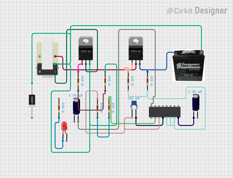
This document provides a detailed overview of an electronic circuit. The circuit comprises various components including capacitors, resistors, MOSFETs, a phase-locked loop IC (CD4046B), a diode, a transformer, an LED, and a battery. The circuit appears to be designed for signal processing or power control, as indicated by the presence of the CD4046B, which is typically used in phase-locked loop systems, and the MOSFETs, which are commonly used for switching and amplification purposes.
Component List
Capacitors
- Ceramic Capacitor
- Capacitance: 0.1 µF (microfarads)
- Electrolytic Capacitors (2x)
- Capacitance: 1 µF (microfarads)
Transistors
- nMOS Transistors (MOSFETs) (2x)
- Type: n-channel MOSFET
Resistors
- Resistors (7x)
- Resistance: 200 Ohms
Integrated Circuits
- CD4046B
- Type: Phase-locked loop IC
Diodes
- 1N4007 Rectifier Diode
- Type: General-purpose rectifier diode
Transformers
- Transformer
- Pin Configuration: 5 pins
LEDs
- LED: Two Pin (red)
- Type: Red LED
Power Sources
- Battery
- Type: General-purpose battery
Wiring Details
Ceramic Capacitor
- Connected to CD4046B COMPin and VCOout.
Electrolytic Capacitors
- One connected to CD4046B Vdd.
- Another connected to CD4046B Vss.
nMOS Transistors (MOSFETs)
- One MOSFET has its gate connected to a resistor and its drain connected to a transformer, while its source is part of a net including a battery, a transformer, a diode, and another resistor.
- The other MOSFET has its gate connected to a resistor and its drain connected to a transformer, while its source is connected to a battery and a resistor.
Resistors
- Multiple resistors are connected in various parts of the circuit, interfacing with the CD4046B, MOSFETs, and other resistors.
CD4046B
- Has connections to ceramic capacitors, electrolytic capacitors, resistors, and its own various pins.
1N4007 Rectifier Diode
- Anode connected to a net with a battery, transformer, MOSFET, and resistor.
Transformer
- Connected to MOSFETs and part of the net with the diode and battery.
LED: Two Pin (red)
- Cathode connected to a resistor.
Battery
- Connected to diode, MOSFETs, and resistors.
Documented Code
There is no embedded code provided for any microcontrollers in this circuit. If there were microcontrollers present, their code would be documented in this section.