
STM32F103C8T6 and MCP2515 CAN Bus Communication System with Raspberry Pi Pico and ESP32 Integration
View and Edit Project In Cirkit Designer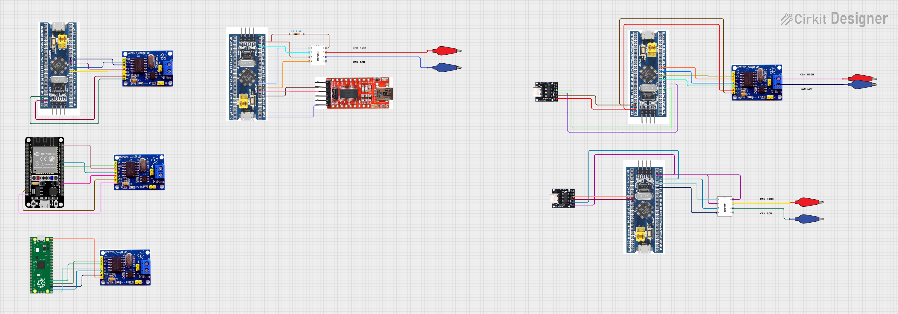
Circuit Documentation
Summary
This document provides a detailed overview of a circuit that integrates multiple microcontrollers and peripheral components. The circuit includes STM32F103C8T6 microcontrollers, MCP2515 CAN controllers, a Raspberry Pi Pico, an ESP32, and various other components. The connections between these components are described in detail, along with the embedded code used in the microcontrollers.
Component List
STM32F103C8T6
- Description: A 32-bit ARM Cortex-M3 microcontroller.
- Pins: GND, 3.3V, reset, B11, B10, B1, B0, A7, A6, A5, A4, A3, A2, A1, A0, C15, C14, C13, VBT, 3.3, 5V, B12, B13, b14, B15, A8, A9, A10, A11, A12, A15, B3, B4, B5, B6, B7, B8, B9, SWIO, SWCLK
MCP2515
- Description: Stand-alone CAN controller with SPI interface.
- Pins: INT, SCK, SI, SO, CS, GND, VCC, H, L
Raspberry Pi Pico
- Description: A low-cost, high-performance microcontroller board with flexible digital interfaces.
- Pins: pin 1, pin 2, pin 3, pin 4, pin 5, pin 6, pin 7, pin 8, pin 9, pin 10, pin 11, pin 12, pin 13, pin 14, pin 15, pin 16, pin 17, pin 18, pin 19, pin 20, pin 21, pin 22, pin 23, pin 24, pin 25, pin 26, pin 27, pin 28, pin 29, pin 30, pin 31, pin 32, pin 33, pin 34, pin 35, pin 36, pin 37, pin 38, pin 39, pin 40, pin 41, pin 42, pin 43
ESP32 (30 pin)
- Description: A low-power system on a chip microcontroller with integrated Wi-Fi and dual-mode Bluetooth.
- Pins: EN, VP, VN, D34, D35, D32, D33, D25, D26, D27, D14, D12, D13, GND, Vin, D23, D22, TX0, RX0, D21, D19, D18, D5, TX2, RX2, D4, D2, D15, 3V3
Serial to USB
- Description: A module to convert serial communication to USB.
- Pins: DTR, RX, TX, VCC, TS, GND
Resistor
- Description: A 10k Ohm resistor.
- Pins: pin1, pin2
- Properties: Resistance: 10000 Ohms
Alligator Clip Cable (Red)
- Description: A red alligator clip cable.
- Pins: Pin, Alligator
Alligator Clip Cable (Blue)
- Description: A blue alligator clip cable.
- Pins: Pin, Alligator
USB Serial TTL
- Description: A USB to TTL serial converter.
- Pins: GND, 5V, TX, RX, DTR, 3.3V
Comment
- Description: A comment component for documentation purposes.
- Pins: None
Wiring Details
STM32F103C8T6
- GND connected to GND of MCP2515
- 5V connected to VCC of MCP2515
- A7 connected to SI of MCP2515
- A6 connected to SO of MCP2515
- A5 connected to SCK of MCP2515
- A4 connected to CS of MCP2515
MCP2515
- SI connected to A7 of STM32F103C8T6
- SO connected to A6 of STM32F103C8T6
- SCK connected to A5 of STM32F103C8T6
- CS connected to A4 of STM32F103C8T6
- GND connected to GND of STM32F103C8T6
- VCC connected to 5V of STM32F103C8T6
Raspberry Pi Pico
- pin 21 connected to SO of MCP2515
- pin 22 connected to CS of MCP2515
- pin 23 connected to GND of MCP2515
- pin 24 connected to SCK of MCP2515
- pin 25 connected to SI of MCP2515
- pin 40 connected to VCC of MCP2515
ESP32 (30 pin)
- GND connected to GND of MCP2515
- Vin connected to VCC of MCP2515
- D23 connected to SI of MCP2515
- D19 connected to SO of MCP2515
- D18 connected to SCK of MCP2515
- D2 connected to CS of MCP2515
Serial to USB
- GND connected to GND of STM32F103C8T6
- RX connected to A9 of STM32F103C8T6
- TX connected to A10 of STM32F103C8T6
Resistor
- pin1 connected to GND of STM32F103C8T6
- pin2 connected to Rs of MCP2515
Alligator Clip Cable (Red)
- Pin connected to CANH of MCP2515
Alligator Clip Cable (Blue)
- Pin connected to CANL of MCP2515
USB Serial TTL
- TX connected to A3 of STM32F103C8T6
- RX connected to A2 of STM32F103C8T6
- GND connected to GND of STM32F103C8T6
- 5V connected to 5V of STM32F103C8T6
Documented Code
Raspberry Pi Pico Code
void setup() {
  // put your setup code here, to run once:

}

void loop() {
  // put your main code here, to run repeatedly:

}
Documentation File
This document provides a comprehensive overview of the circuit, including the components used, their connections, and the embedded code. This should serve as a useful reference for understanding and replicating the circuit.