Cirkit Designer
Your all-in-one circuit design IDE
Home /
Project Documentation
Arduino-Controlled Dual Motor Driver Circuit with Voltage Regulation and Indicator LED

Circuit Documentation
Summary
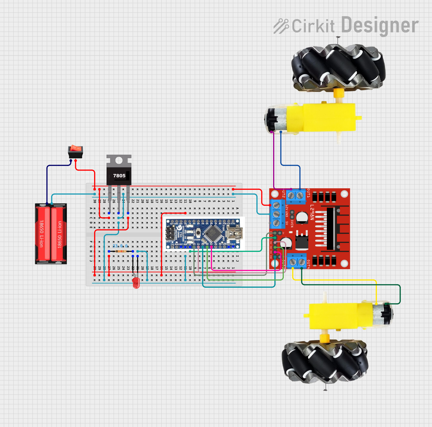
This circuit is designed to control a pair of motors using an L298N DC motor driver, which is interfaced with an Arduino Nano microcontroller. The power supply for the motor driver is regulated by a 7805 voltage regulator, and the circuit includes a rocker switch to control the power flow. Additionally, there is an LED indicator with a current-limiting resistor. The power source for the circuit is an 18650 Li-Ion battery.
Component List
7805 Voltage Regulator
- Pins: Vin, Gnd, Vout
- Description: A voltage regulator that outputs a steady 5V from a higher voltage input.
Resistor
- Pins: pin1, pin2
- Description: A passive two-terminal electrical component that implements electrical resistance as a circuit element.
- Resistance: 33 Ohms
LED: Two Pin (red)
- Pins: cathode, anode
- Description: A red light-emitting diode used as an indicator.
L298N DC Motor Driver
- Pins: OUT1, OUT2, 12V, GND, 5V, OUT3, OUT4, 5V-ENA-JMP-I, 5V-ENA-JMP-O, +5V-J1, +5V-J2, ENA, IN1, IN2, IN3, IN4, ENB
- Description: A module that can control up to two DC motors with individual speed and direction control.
Arduino Nano
- Pins: D12, D11, D10, D9, D8, D7, D6, D5, D4, D3, D2, GND, RST, RX0, TX1, D13, 3V3, REF, A0, A1, A3, A4, A5, A6, A7, 5V, VIN
- Description: A small, complete, and breadboard-friendly board based on the ATmega328 (Arduino Nano 3.x).
18650 Li-Ion Battery
- Pins: Positive, Negative
- Description: A rechargeable lithium-ion battery used as the power source for the circuit.
Rocker Switch
- Pins: output, input
- Description: A switch used to control the connection of the circuit to the power source.
Motor and Wheels (2 instances)
- Pins: vcc, GND
- Description: The output devices of the circuit, which are driven by the motor driver.
Wiring Details
7805 Voltage Regulator
- Vin: Connected to the rocker switch output.
- Gnd: Connected to the common ground net.
- Vout: Connected to the anode of the LED through a 33 Ohm resistor.
Resistor
- pin1: Connected to the Vout of the 7805 voltage regulator.
- pin2: Connected to the anode of the LED.
LED: Two Pin (red)
- cathode: Connected to the common ground net.
- anode: Connected to pin2 of the resistor.
L298N DC Motor Driver
- 12V: Connected to the Vin of the 7805 voltage regulator.
- GND: Connected to the common ground net.
- OUT1, OUT2: Connected to one instance of the motor and wheels.
- OUT3, OUT4: Connected to the other instance of the motor and wheels.
- ENA, IN1, IN2, IN3, IN4, ENB: Controlled by the Arduino Nano digital pins.
Arduino Nano
- D2, D3, D4, D5, D6, D7: Control signals for the L298N DC motor driver.
- GND: Connected to the common ground net.
18650 Li-Ion Battery
- Positive: Connected to the input of the rocker switch.
- Negative: Connected to the common ground net.
Rocker Switch
- output: Connected to the Vin of the 7805 voltage regulator.
- input: Connected to the Positive pin of the 18650 Li-Ion battery.
Motor and Wheels
- vcc: Connected to OUT2 and OUT4 of the L298N DC motor driver for each instance.
- GND: Connected to OUT1 and OUT3 of the L298N DC motor driver for each instance.
Documented Code
There is no code provided for the microcontroller in this circuit. The Arduino Nano would typically be programmed to control the L298N DC motor driver, setting the direction and speed of the motors based on the logic implemented in the code. Since no code is available, this section cannot be documented further.