Cirkit Designer
Your all-in-one circuit design IDE
Home /
Project Documentation
Arduino-Controlled Firefighting Robot with Bluetooth and Ultrasonic Sensing
Circuit Documentation
Summary
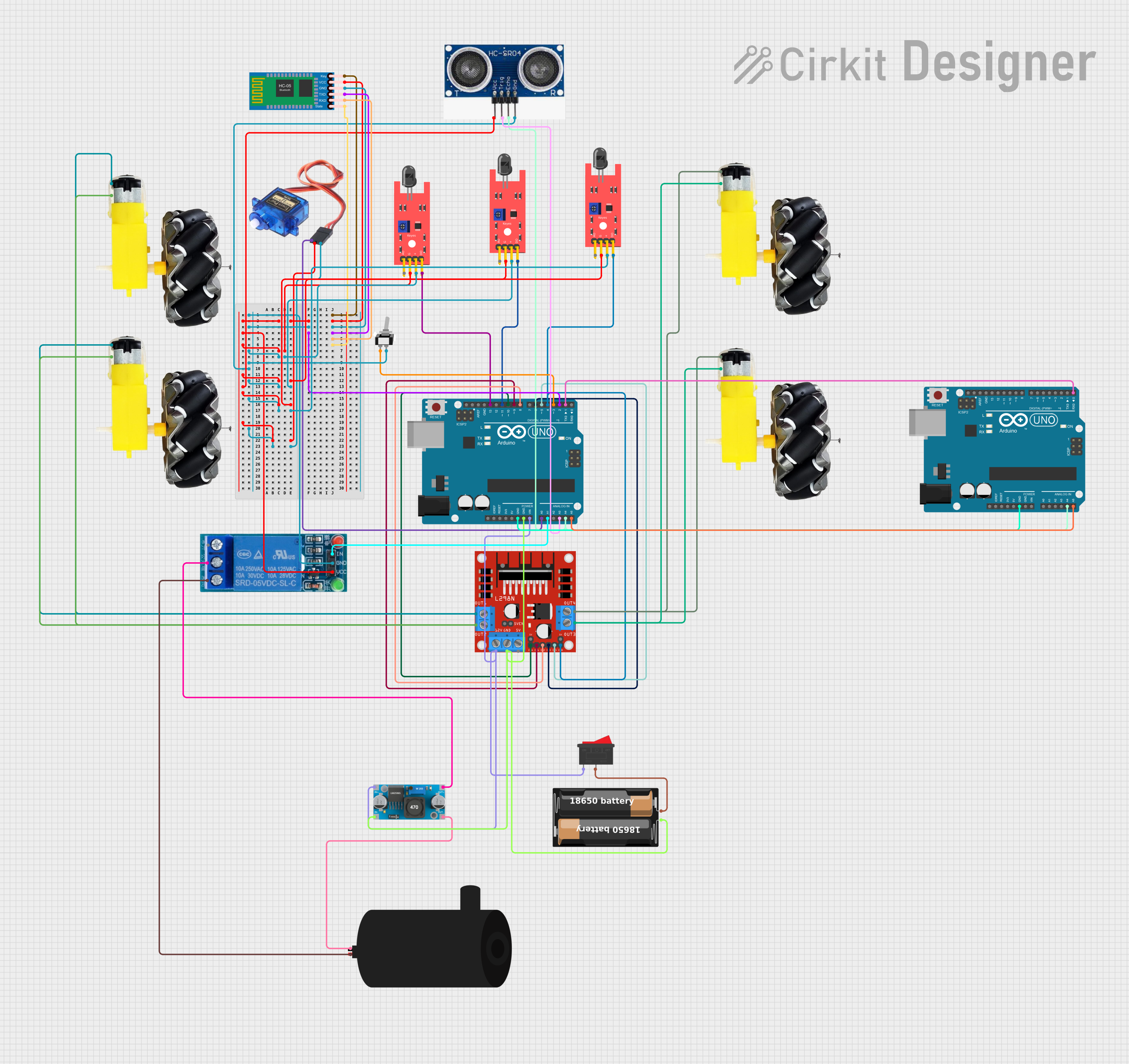
This circuit is designed to control a robot with various sensors and actuators. It includes flame sensors for fire detection, a motor driver for wheel movement, a water pump for fire extinguishing, an ultrasonic sensor for distance measurement, and a Bluetooth module for wireless communication. The brain of the robot is an Arduino UNO microcontroller, which processes sensor data and controls actuators accordingly. The circuit is powered by a battery case, and voltage regulation is managed by an LM2596 buck converter. A relay is used to control the water pump, and switches are included for manual control.
Component List
Sensors
- KY-026 Flame Sensor: Detects the presence of a flame or fire.
- Ultrasonic Sensor: Measures the distance to an object by using ultrasonic waves.
Actuators
- Motor and Wheels: Provides movement to the robot.
- Servo Motor: Controls precise movement, possibly for a sensor or an arm.
- Water Pump: Used to extinguish fires detected by the flame sensors.
Control
- Arduino UNO: The main microcontroller board that controls the robot.
- HC-05 Bluetooth Module: Allows for wireless communication with the robot.
- L298N DC Motor Driver: Controls the direction and speed of the motors.
- Relay 5V Single Connection: Electrically operated switch to control the water pump.
Power
- My Battery Case: Provides power to the circuit.
- LM2596 Buck Converter: Steps down voltage to a lower level.
Switches
- Rocker Switch: A manual switch to control power flow.
- Toggle Switch SPST: A single-pole single-throw switch for controlling a circuit.
Wiring Details
KY-026 Flame Sensor
- VCC: Connected to the power supply.
- GND: Connected to the ground.
- D0: Digital output connected to the Arduino UNO for flame detection.
- A0: Analog output, not used in this circuit.
Ultrasonic Sensor
- Vcc: Connected to the power supply.
- Trigger: Connected to an Arduino UNO pin for initiating the ultrasonic pulse.
- Echo: Connected to an Arduino UNO pin for receiving the ultrasonic pulse.
- Gnd: Connected to the ground.
Motor and Wheels
- VCC: Connected to the motor driver output for power.
- GND: Connected to the motor driver output for ground.
Servo Motor
- Power: Connected to the power supply.
- Ground: Connected to the ground.
- Signal: Connected to an Arduino UNO pin for control signals.
Water Pump
- Positive: Connected to the normally closed (NC) terminal of the relay.
- Negative: Connected to the ground through the LM2596 buck converter.
Arduino UNO
- Digital and Analog Pins: Connected to various components for control and sensing.
- GND: Connected to the ground.
- Vin: Connected to the power supply through a switch and voltage regulator.
- 5V and 3.3V: Provide regulated power to components.
HC-05 Bluetooth Module
- VCC: Connected to the power supply.
- GND: Connected to the ground.
- TXD: Transmits data to the Arduino UNO.
- RXD: Receives data from the Arduino UNO.
- Key, State: Not used in this circuit.
L298N DC Motor Driver
- IN1, IN2, IN3, IN4: Control inputs connected to Arduino UNO pins.
- ENA, ENB: Enable pins connected to Arduino UNO pins for speed control.
- OUT1, OUT2, OUT3, OUT4: Outputs connected to the motors.
Relay 5V Single Connection
- VCC: Connected to the power supply.
- GND: Connected to the ground.
- IN: Control input connected to an Arduino UNO pin.
- NO, COMM, NC: Normally open, common, and normally closed terminals for switching.
LM2596 Buck Converter
- IN +, IN -: Input connected to the battery case.
- OUT +, OUT -: Output connected to the water pump and relay.
Rocker Switch
- 1, 2: Connected between the battery case and the circuit to control power flow.
Toggle Switch SPST
- L1, COM: Connected to an Arduino UNO pin for manual control.
Documented Code
Arduino UNO (Main Controller)
#include <Wire.h>
#include <Servo.h>
#include <Adafruit_MLX90614.h>
#include <SoftwareSerial.h>

// Define Ultrasonic Sensor Pins
#define TRIG_PIN A3
#define ECHO_PIN A2

Adafruit_MLX90614 mlx = Adafruit_MLX90614();

// Define pins for flame sensors
#define FLAME_SENSOR_LEFT 4
#define FLAME_SENSOR_RIGHT 13
#define FLAME_SENSOR_FRONT 11

#define LM1 6  // Left motor forward
#define LM2 7  // Left motor backward
#define RM1 8  // Right motor forward
#define RM2 9  // Right motor backward
#define PUMP_PIN A1 // Water pump

#define enA 5  // Enable pin for left motor
#define enB 10 // Enable pin for right motor

#define BUZZER_PIN 3  // Buzzer pin

#define BLUETOOTH_RX 12
#define BLUETOOTH_TX 2

// Distance threshold to stop the robot (in cm)
#define DISTANCE_THRESHOLD 20

// Create SoftwareSerial object for Bluetooth communication
SoftwareSerial bluetooth(BLUETOOTH_TX, BLUETOOTH_RX);

void setup() {
  // Initialize serial communication for Bluetooth
  bluetooth.begin(9600);
  Serial.begin(9600);

  // Motor pins setup
  pinMode(LM1, OUTPUT);
  pinMode(LM2, OUTPUT);
  pinMode(RM1, OUTPUT);
  pinMode(RM2, OUTPUT);

  // Sensors and actuators setup
  pinMode(FLAME_SENSOR_LEFT, INPUT);
  pinMode(FLAME_SENSOR_RIGHT, INPUT);
  pinMode(FLAME_SENSOR_FRONT, INPUT);
  pinMode(BUZZER_PIN, OUTPUT);
  pinMode(PUMP_PIN, OUTPUT);

  // Ultrasonic sensor setup
  pinMode(TRIG_PIN, OUTPUT);
  pinMode(ECHO_PIN, INPUT);

  // Initialize actuators to be off
  digitalWrite(BUZZER_PIN, LOW);
  digitalWrite(PUMP_PIN, LOW);

  // Initialize MLX90614 sensor
  mlx.begin();
}

void loop() {
  // Read flame sensor values (digital)
  bool leftFlame = digitalRead(FLAME_SENSOR_LEFT);
  bool rightFlame = digitalRead(FLAME_SENSOR_RIGHT);
  bool frontFlame = digitalRead(FLAME_SENSOR_FRONT);

  // Measure distance using the ultrasonic sensor
  long distance = measureDistance();  // This will also print the distance to the Serial Monitor

  // Robot movement logic
  if (distance <= DISTANCE_THRESHOLD) {  // Obstacle detected within threshold
    stopRobot();
    if (!frontFlame) {  // Flame detected in front after stopping
      extinguishFire();
    }
  } else if (!frontFlame) {  // Flame detected in front
    moveForward();
  } else if (!leftFlame) {  // Flame detected on the left
    moveRight();
  } else if (!rightFlame) {  // Flame detected on the right
    moveLeft();
  } else {  // No flame detected
    stopRobot();
  }

  // Bluetooth control
  if (bluetooth.available()) {
    char command = bluetooth.read();
    controlRobotViaBluetooth(command);
  }
}

void moveForward() {
  Serial.println("Moving Forward");
  analogWrite(enA, 120); // Write The Duty Cycle 0 to 255 Enable Pin A for Motor1 Speed
  analogWrite(enB, 120);
  digitalWrite(LM1, LOW);
  digitalWrite(LM2, HIGH);
  digitalWrite(RM1, LOW);
  digitalWrite(RM2, HIGH);
}

void moveLeft() {
  Serial.println("Turning Left");
  analogWrite(enA, 200); // Write The Duty Cycle 0 to 255 Enable Pin A for Motor1 Speed
  analogWrite(enB, 200);
  digitalWrite(LM1, LOW); // Left Motor backward Pin
  digitalWrite(LM2, LOW); // Left Motor forward Pin
  digitalWrite(RM1, LOW); // Right Motor forward Pin
  digitalWrite(RM2, HIGH); // Right Motor backward Pin
}

void moveRight() {
  Serial.println("Turning Right");
  analogWrite(enA, 200); // Reduce speed for turning
  analogWrite(enB, 200); // Reduce speed for turning
  digitalWrite(LM1, LOW); // Left Motor backward Pin
  digitalWrite(LM2, HIGH); // Left Motor forward Pin
  digitalWrite(RM1, LOW); // Right Motor forward Pin
  digitalWrite(RM2, LOW); // Right Motor backward Pin
}

void stopRobot() {
  Serial.println("Stopping Robot");
  digitalWrite(LM1, LOW);
  digitalWrite(LM2, LOW);
  digitalWrite(RM1, LOW);
  digitalWrite(RM2, LOW);
}

void extinguishFire() {
  Serial.println("Extinguishing Fire");
  // Activate buzzer and pump for fire