
Circuit Documentation
Summary
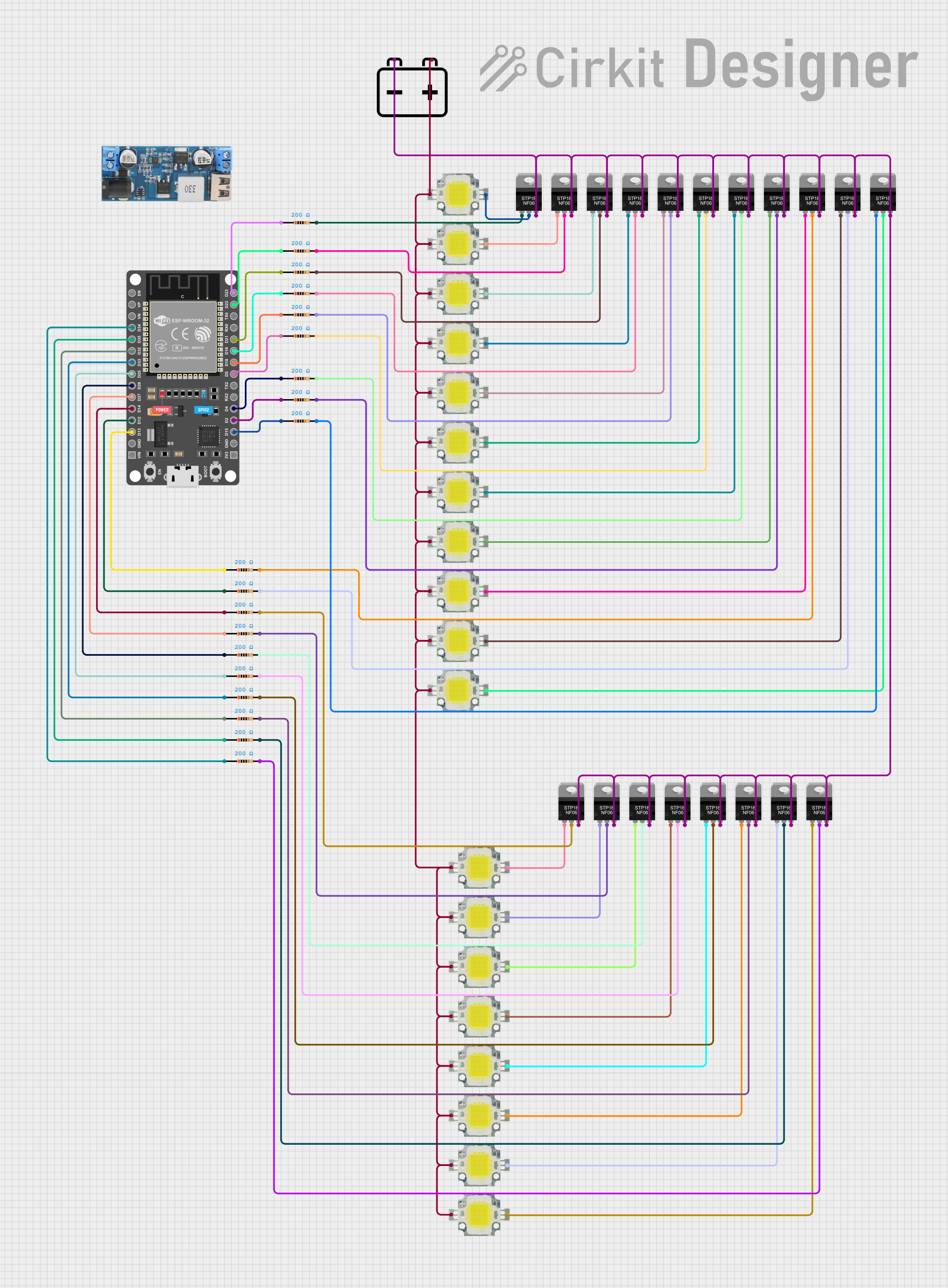
This circuit is designed to control multiple high-power LEDs using an ESP32 microcontroller and N-Channel Power MOSFETs. The circuit includes resistors to limit current and a 12V battery to power the LEDs. The ESP32 microcontroller is used to control the gates of the MOSFETs, which in turn control the LEDs.
Component List
Power LED 12V 10W 0.8-0.9A
- Pins: +, -
- Description: High-power LED
- Purpose: Provides illumination
STP16NF06 N-Channel Power MOSFET
- Pins: gate, drain, source
- Description: N-Channel MOSFET
- Purpose: Switches the LEDs on and off
Resistor
- Pins: pin1, pin2
- Description: 200 Ohms resistor
- Purpose: Limits current to the MOSFET gate
12V Battery
- Pins: +, -
- Description: 12V power source
- Purpose: Powers the LEDs
ESP 32 DEVKIT V1 (30 pins)
- Pins: EN, VP, VN, D34, D35, D32, D33, D25, D26, D27, D14, D12, D13, GND, VIN, 3V3, D15, D2, D4, RX2, TX2, D5, D18, D19, D21, RX0, TX0, D22, D23
- Description: Microcontroller
- Purpose: Controls the MOSFETs
12v to 5v Step Down Power Converter
- Pins: VIN 9v-36v, VIN+, VIN-, USB OUTPUT 5V, 5v OUTPUT, GND
- Description: Voltage converter
- Purpose: Converts 12V to 5V for the ESP32
Wiring Details
Power LED 12V 10W 0.8-0.9A
+ Pin:
- Connected to the + pin of the 12V Battery
- Connected to the + pins of all other Power LEDs
- Pin:
- Connected to the drain pin of the corresponding STP16NF06 N-Channel Power MOSFET
STP16NF06 N-Channel Power MOSFET
Gate Pin:
- Connected to pin2 of the corresponding Resistor
Drain Pin:
- Connected to the - pin of the corresponding Power LED
Source Pin:
- Connected to the - pin of the 12V Battery
- Connected to the source pins of all other STP16NF06 N-Channel Power MOSFETs
Resistor
Pin1:
- Connected to the corresponding GPIO pin of the ESP 32 DEVKIT V1 (30 pins)
Pin2:
- Connected to the gate pin of the corresponding STP16NF06 N-Channel Power MOSFET
12V Battery
+ Pin:
- Connected to the + pin of all Power LEDs
- Pin:
- Connected to the source pin of all STP16NF06 N-Channel Power MOSFETs
ESP 32 DEVKIT V1 (30 pins)
D34 Pin:
- Connected to pin1 of a Resistor
D35 Pin:
- Connected to pin1 of a Resistor
D32 Pin:
- Connected to pin1 of a Resistor
D33 Pin:
- Connected to pin1 of a Resistor
D25 Pin:
- Connected to pin1 of a Resistor
D26 Pin:
- Connected to pin1 of a Resistor
D27 Pin:
- Connected to pin1 of a Resistor
D14 Pin:
- Connected to pin1 of a Resistor
D12 Pin:
- Connected to pin1 of a Resistor
D13 Pin:
- Connected to pin1 of a Resistor
D15 Pin:
- Connected to pin1 of a Resistor
D2 Pin:
- Connected to pin1 of a Resistor
D4 Pin:
- Connected to pin1 of a Resistor
D5 Pin:
- Connected to pin1 of a Resistor
D18 Pin:
- Connected to pin1 of a Resistor
D19 Pin:
- Connected to pin1 of a Resistor
D21 Pin:
- Connected to pin1 of a Resistor
D22 Pin:
- Connected to pin1 of a Resistor
D23 Pin:
- Connected to pin1 of a Resistor
12v to 5v Step Down Power Converter
VIN 9v-36v Pin:
- Connected to the + pin of the 12V Battery
VIN+ Pin:
- Connected to the + pin of the 12V Battery
VIN- Pin:
- Connected to the - pin of the 12V Battery
USB OUTPUT 5V Pin:
- Not connected
5v OUTPUT Pin:
- Connected to the VIN pin of the ESP 32 DEVKIT V1 (30 pins)
GND Pin:
- Connected to the GND pin of the ESP 32 DEVKIT V1 (30 pins)
Code
No code provided.