Arduino Mega 2560-Based Multi-Sensor Robotic Controller with Visual Indicators
Circuit Documentation
Summary
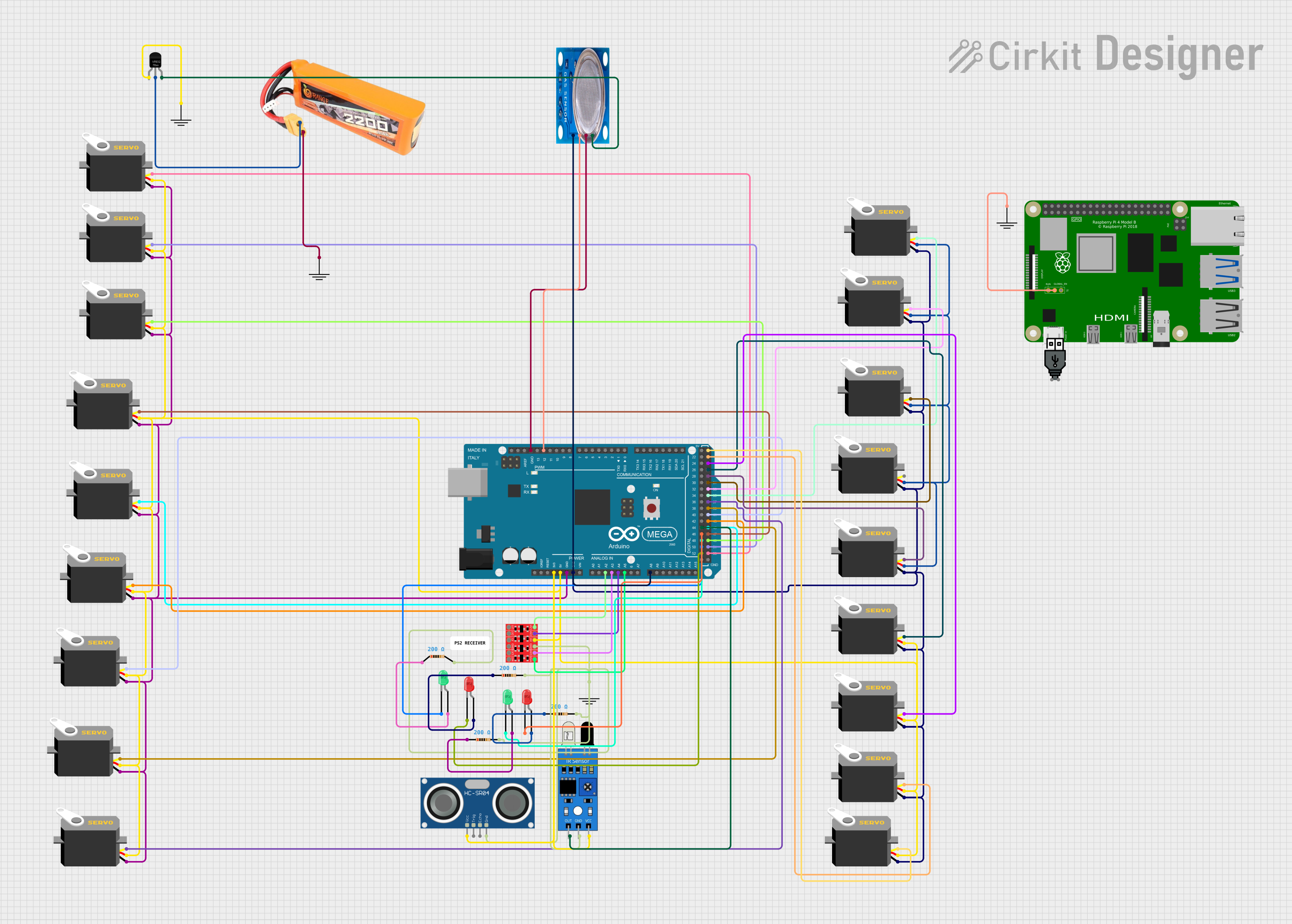
The circuit in question appears to be a complex system involving an Arduino Mega 2560 microcontroller, multiple servos, sensors (including an HC-SR04 Ultrasonic Sensor, an IR sensor, and an MQ-5 gas sensor), LEDs, a logic level converter, resistors, a voltage regulator, a LiPo battery, and a Raspberry Pi 4B. The Arduino Mega 2560 is the central processing unit, interfacing with the servos and sensors, and controlling the LEDs. The Raspberry Pi may serve as a higher-level controller or for tasks such as data processing, networking, or user interface. The voltage regulator ensures that components receive the correct voltage from the LiPo battery.
Component List
- Arduino Mega 2560: A microcontroller board based on the ATmega2560, with numerous digital and analog I/O pins.
- Servo: A rotary actuator or linear actuator that allows for precise control of angular or linear position.
- HC-SR04 Ultrasonic Sensor: A sensor that measures distance by emitting ultrasonic waves and measuring the time taken for the echo to return.
- IR Sensor: An infrared sensor that can detect infrared light, often used in proximity sensors.
- LED (Green and Red): Light-emitting diodes that emit green and red light, respectively.
- Bi-Directional Logic Level Converter: A device that safely steps down 5V signals to 3.3V and steps up 3.3V to 5V simultaneously.
- Resistor: A passive two-terminal electrical component that implements electrical resistance as a circuit element.
- MQ-5 Gas Sensor: A gas sensor used for gas leakage detecting equipment in family and industry, detecting LPG, natural gas, town gas.
- LiPo Battery 2200mAh 30C: A rechargeable battery of Lithium Polymer (LiPo) type with a capacity of 2200mAh.
- Raspberry Pi 4B: A small single-board computer with a broad set of capabilities including GPIO pins.
- Voltage Regulator: An electronic device that maintains a constant voltage level to its load.
Wiring Details
Arduino Mega 2560
- Connected to 3.3V: HC-SR04 Ultrasonic Sensor (VCC), IR Sensor (VCC)
- Connected to 5V: Multiple Servos (VCC), Bi-Directional Logic Level Converter (HV), MQ-5 Gas Sensor (VCC)
- Connected to GND: Multiple Servos (GND), HC-SR04 Ultrasonic Sensor (GND), IR Sensor (GND), Bi-Directional Logic Level Converter (GND), MQ-5 Gas Sensor (GND)
- Connected to Analog Pins:
- A2: Bi-Directional Logic Level Converter (HV1)
- A3: Bi-Directional Logic Level Converter (HV3)
- A4: Bi-Directional Logic Level Converter (HV2)
- A5: Bi-Directional Logic Level Converter (HV4)
- A8: MQ-5 Gas Sensor (Analog out)
- Connected to Digital Pins:
- D12: MQ-5 Gas Sensor (Digi Out)
- D44: IR Sensor (out)
- D52, D50, D48, D46: LEDs (cathode)
- D53, D51, D49, D47, D45, D43, D41, D39, D37, D35, D33, D31, D29, D27, D25, D23: Servos (pulse)
Servos
- All servos are connected to a common 5V and GND line for power.
- Each servo's pulse line is connected to a unique digital PWM-capable pin on the Arduino Mega 2560.
Sensors
- HC-SR04 Ultrasonic Sensor: VCC connected to 3.3V, GND to GND, TRIG and ECHO pins not detailed in the net list.
- IR Sensor: VCC connected to 3.3V, GND to GND, and OUT to D44 on the Arduino Mega 2560.
- MQ-5 Gas Sensor: VCC connected to 5V via the voltage regulator, GND to GND, Analog out to A8, and Digi Out to D12 on the Arduino Mega 2560.
LEDs
- Each LED's cathode is connected to a unique digital pin on the Arduino Mega 2560.
- Each LED's anode is connected to a 200 Ohm resistor, which is then connected to GND.
Logic Level Converter
- HV connected to 5V, GND to GND.
- HV1, HV2, HV3, HV4 connected to A2, A4, A3, A5 on the Arduino Mega 2560, respectively.
Voltage Regulator
- IN connected to the LiPo battery VCC, GND to the battery GND, and OUT to the MQ-5 Gas Sensor VCC.
Raspberry Pi 4B
- GND connected to a common GND line.
Documented Code
Arduino Mega 2560 (sketch.ino)
void setup() {
  // put your setup code here, to run once:

}

void loop() {
  // put your main code here, to run repeatedly:

}
Note: The provided code for the Arduino Mega 2560 is a template with empty setup and loop functions. Actual functionality needs to be implemented based on the requirements of the circuit.