
Arduino Nano and ESP8266 Wi-Fi Controlled LED Strip with MPU-6050
View and Edit Project In Cirkit Designer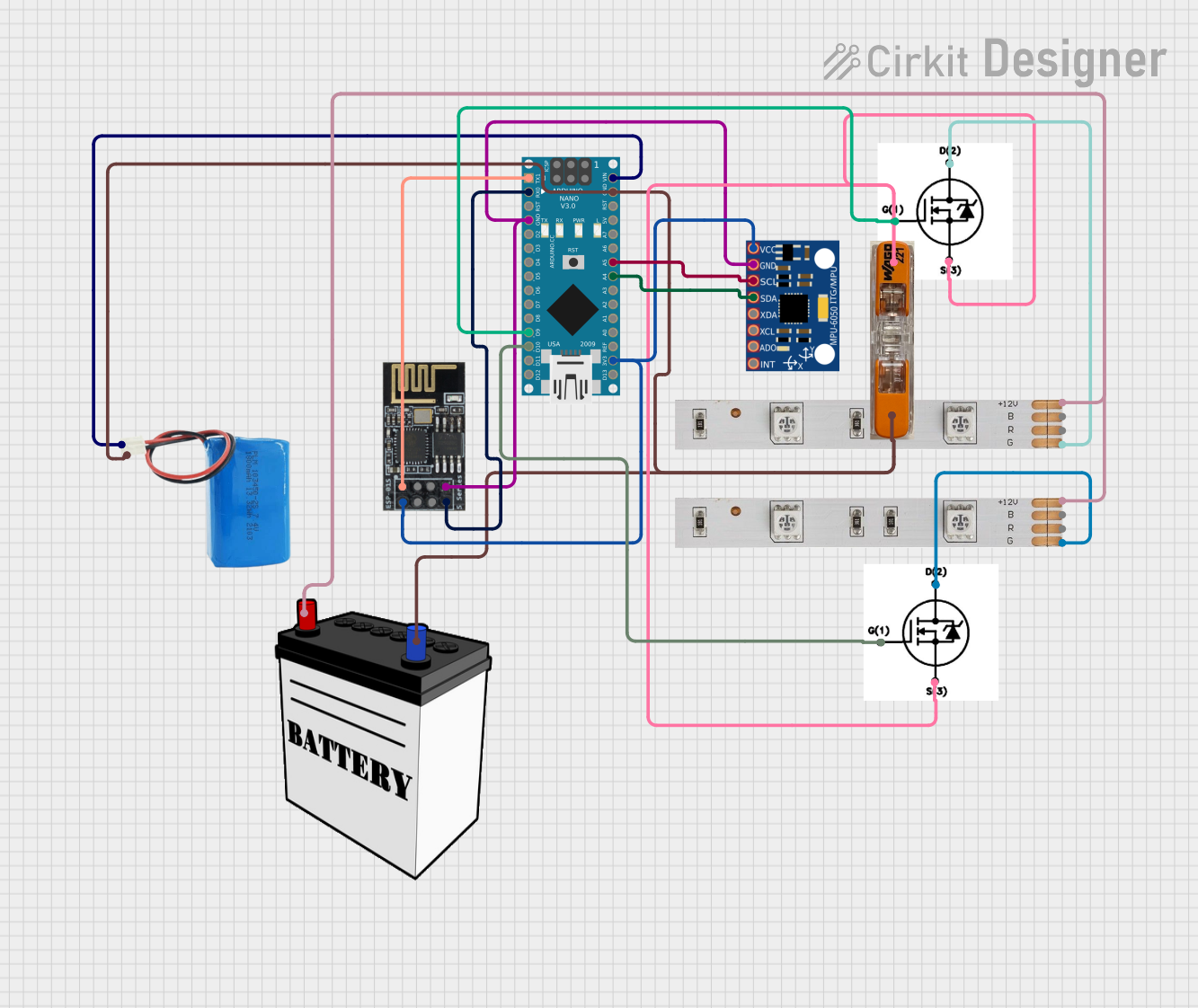
Circuit Documentation
Summary
This circuit involves an Arduino Nano microcontroller interfacing with an MPU-6050 sensor, an ESP8266-01 WiFi module, and two LED strips controlled via N-Channel MOSFETs. The circuit is powered by a 5V battery and a 12V battery. The Arduino Nano is responsible for controlling the LED strips and communicating with the MPU-6050 sensor and the ESP8266-01 WiFi module.
Component List
5V Battery
- Description: Provides 5V power to the Arduino Nano.
- Pins: Positive, Negative
Arduino Nano
- Description: Microcontroller used to control the circuit.
- Pins: D1/TX, D0/RX, RESET, GND, D2, D3, D4, D5, D6, D7, D8, D9, D10, D11/MOSI, D12/MISO, VIN, 5V, A7, A6, A5, A4, A3, A2, A1, A0, AREF, 3V3, D13/SCK
MPU-6050
- Description: 6-axis motion tracking device.
- Pins: VCC, GND, SCL, SDA, XDA, XCL, AD0, INT
WiFi Module ESP8266-01
- Description: WiFi module for wireless communication.
- Pins: RX, GPIO0, GPIO2, GND, +3V3, Reset, CH-PD Chip power down, TX
LED Strip (1)
- Description: RGB LED strip.
- Pins: B, +12V, R, G
LED Strip (2)
- Description: RGB LED strip.
- Pins: B, +12V, R, G
N-Channel MOSFET IRFZ44N (1)
- Description: MOSFET used to control the LED strip.
- Pins: Drain, Source, Gate
N-Channel MOSFET IRFZ44N (2)
- Description: MOSFET used to control the LED strip.
- Pins: Drain, Source, Gate
12V Battery
- Description: Provides 12V power to the LED strips.
- Pins: VCC, GND
WAGO Connector
- Description: Electrical connector for joining wires.
- Pins: AWG 18-14
Wiring Details
5V Battery
- Positive: Connected to Arduino Nano VIN
- Negative: Connected to WAGO Connector, Arduino Nano GND
Arduino Nano
- VIN: Connected to 5V Battery Positive
- GND: Connected to WAGO Connector, MPU-6050 GND, ESP8266-01 GND
- D1/TX: Connected to ESP8266-01 RX
- D0/RX: Connected to ESP8266-01 TX
- D9: Connected to N-Channel MOSFET IRFZ44N (1) Gate
- D10: Connected to N-Channel MOSFET IRFZ44N (2) Gate
- A5: Connected to MPU-6050 SCL
- A4: Connected to MPU-6050 SDA
- 3V3: Connected to MPU-6050 VCC, ESP8266-01 +3V3
MPU-6050
- VCC: Connected to Arduino Nano 3V3
- GND: Connected to Arduino Nano GND
- SCL: Connected to Arduino Nano A5
- SDA: Connected to Arduino Nano A4
WiFi Module ESP8266-01
- RX: Connected to Arduino Nano D1/TX
- TX: Connected to Arduino Nano D0/RX
- GND: Connected to Arduino Nano GND
- +3V3: Connected to Arduino Nano 3V3
LED Strip (1)
- +12V: Connected to 12V Battery VCC
- G: Connected to N-Channel MOSFET IRFZ44N (1) Drain
LED Strip (2)
- +12V: Connected to 12V Battery VCC
- G: Connected to N-Channel MOSFET IRFZ44N (2) Drain
N-Channel MOSFET IRFZ44N (1)
- Gate: Connected to Arduino Nano D9
- Drain: Connected to LED Strip (1) G
- Source: Connected to WAGO Connector
N-Channel MOSFET IRFZ44N (2)
- Gate: Connected to Arduino Nano D10
- Drain: Connected to LED Strip (2) G
- Source: Connected to WAGO Connector
12V Battery
- VCC: Connected to LED Strip (1) +12V, LED Strip (2) +12V
- GND: Connected to WAGO Connector
WAGO Connector
- AWG 18-14: Connected to 12V Battery GND, 5V Battery Negative, Arduino Nano GND, N-Channel MOSFET IRFZ44N (1) Source, N-Channel MOSFET IRFZ44N (2) Source
Documented Code
Arduino Nano Code (sketch.ino)
void setup() {
  // put your setup code here, to run once:

}

void loop() {
  // put your main code here, to run repeatedly:

}
Additional Documentation (documentation.txt)