ESP32-Based Security System with RFID, PIR Sensor, and Laser Detection
Circuit Documentation
Summary
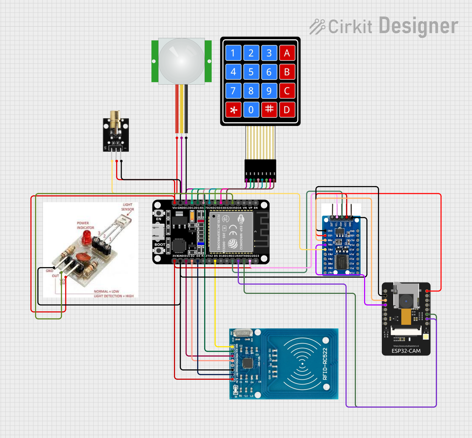
This circuit integrates various components to perform a range of functions, including motion detection, RFID scanning, keypad input, and image capture. The central processing unit is an ESP32 microcontroller, which interfaces with a PIR sensor for motion detection, an RFID-RC522 module for RFID tag reading, a 4x4 membrane matrix keypad for user input, an ESP32-CAM module for image capture, a PCF8575 I/O expander to increase the number of available I/O pins, a KY-008 laser emitter, and a laser receiver module to detect laser beam interruption.
Component List
ESP32 (30 pin)
- A 30-pin microcontroller with Wi-Fi and Bluetooth capabilities, used as the main processing unit for the circuit.
PIR Sensor
- A motion sensor that detects changes in infrared levels caused by moving objects, typically used for motion detection.
RFID-RC522
- An RFID reader/writer module that operates at 13.56 MHz, used for scanning RFID tags.
4X4 Membrane Matrix Keypad
- A 16-button keypad that provides user input to the microcontroller.
ESP32-CAM
- A small camera module with an ESP32 microcontroller, capable of capturing images and video.
PCF8575 I/O Expander
- An I2C interface I/O expander that provides additional digital input/output pins.
KY-008 Laser Emitter
- A module that emits a laser beam, used in conjunction with the laser receiver module.
Laser Receiver Module
- A module that detects the presence of a laser beam, used to detect interruptions in the beam.
Wiring Details
ESP32 (30 pin)
- D35 connected to Laser Receiver Module OUTPUT
- D32 connected to 4X4 Keypad C4
- D33 connected to 4X4 Keypad C3
- D25 connected to 4X4 Keypad C2
- D26 connected to 4X4 Keypad C1
- D27 connected to 4X4 Keypad R4
- D14 connected to RFID-RC522 SCK and 4X4 Keypad R3
- D12 connected to 4X4 Keypad R2
- D13 connected to PIR Sensor SIG and 4X4 Keypad R1
- GND connected to KY-008 Laser Emitter GND, PIR Sensor GND, Laser Receiver Module GROUND, RFID-RC522 GND, PCF8575 I/O Expander GND
- Vin connected to Laser Receiver Module VCC, KY-008 Laser Emitter 5V, PIR Sensor VDD
- D22 connected to PCF8575 I/O Expander SCL
- TX0 connected to ESP32-CAM VOR
- RX0 connected to ESP32-CAM VOT
- D21 connected to PCF8575 I/O Expander SDA
- D5 connected to RFID-RC522 SDA
- D4 connected to RFID-RC522 RST
- D2 connected to RFID-RC522 MISO
- D15 connected to RFID-RC522 MOSI
- 3V3 connected to RFID-RC522 VCC (3.3V), PCF8575 I/O Expander VCC
ESP32-CAM
- GND connected to PCF8575 I/O Expander GND
- IO12 connected to PCF8575 I/O Expander P00
- IO13 connected to PCF8575 I/O Expander P01
- 3V3 connected to PCF8575 I/O Expander VDD
PCF8575 I/O Expander
- P02 connected to KY-008 Laser Emitter SIG
Documented Code
No code has been provided for the microcontrollers in the circuit. The documentation of the code would typically include descriptions of the functionality implemented, setup and loop functions, and any libraries or external dependencies used. It would also detail the logic for interfacing with each of the components, handling inputs and outputs, and any communication protocols used (e.g., I2C, SPI, UART).