ESP32-Based Power Monitoring and Relay Control System
Circuit Documentation
Summary
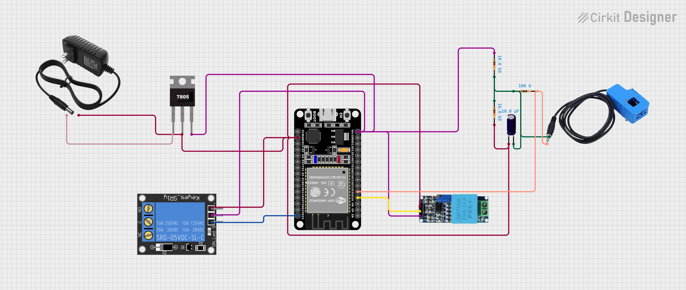
This circuit integrates various components including an ESP32 microcontroller, a 1-Channel Relay, current and voltage sensors, resistors, an electrolytic capacitor, a 12V power supply, and a 7805 voltage regulator. The ESP32 is used as the central processing unit, interfacing with sensors to monitor current and voltage levels, and controlling a relay for power management. The resistors and capacitor form a filtering network, and the 7805 regulator steps down the voltage from the 12V power supply to 5V required by some components.
Component List
ESP32 (30 pin)
- Description: A microcontroller with WiFi and Bluetooth capabilities.
- Pins: EN, VP, VN, D34, D35, D32, D33, D25, D26, D27, D14, D12, D13, GND, Vin, D23, D22, TX0, RX0, D21, D19, D18, D5, TX2, RX2, D4, D2, D15, 3V3
1-Channel Relay (5V 10A)
- Description: An electromechanical switch that can be controlled by the ESP32.
- Pins: NC, signal, C, power, NO, ground
Current Sensor
- Description: A sensor for measuring electrical current.
- Pins: Out, Burden, In_current, Out_current
Voltage Sensor
- Description: A sensor for measuring voltage levels.
- Pins: Ground, Phase, Vcc, Out, Gnd
Resistor (10k Ohms)
- Description: A passive two-terminal electrical component that implements electrical resistance.
- Pins: pin1, pin2
- Resistance: 10,000 Ohms
Resistor (100 Ohms)
- Description: A passive two-terminal electrical component that implements electrical resistance.
- Pins: pin1, pin2
- Resistance: 100 Ohms
Electrolytic Capacitor
- Description: A capacitor that uses an electrolyte to achieve a larger capacitance.
- Pins: -, +
- Capacitance: 0.00001 Farads
12V Power Supply
- Description: Provides a 12V voltage source.
- Pins: +, -
7805 Voltage Regulator
- Description: A voltage regulator that outputs a stable 5V from a higher voltage input.
- Pins: Vin, Gnd, Vout
Wiring Details
ESP32 (30 pin)
- D34 connected to Voltage Sensor Out
- D35 connected to Current Sensor Out and Resistor (100 Ohms) pin2
- Vin connected to 1-Channel Relay power, 7805 Vout, Voltage Sensor Vcc, and Resistor (10k Ohms) pin1
- D23 connected to 1-Channel Relay signal
- GND connected to 1-Channel Relay ground, 7805 Gnd, Voltage Sensor Gnd, 12V Power Supply -, Electrolytic Capacitor -, and Resistor (10k Ohms) pin2
1-Channel Relay (5V 10A)
- Power connected to ESP32 Vin, 7805 Vout, Voltage Sensor Vcc, and Resistor (10k Ohms) pin1
- Signal connected to ESP32 D23
- Ground connected to ESP32 GND, 7805 Gnd, Voltage Sensor Gnd, 12V Power Supply -, Electrolytic Capacitor -, and Resistor (10k Ohms) pin2
Current Sensor
- Out connected to ESP32 D35 and Resistor (100 Ohms) pin2
- Burden connected to Resistor (100 Ohms) pin1, Electrolytic Capacitor +, and Resistor (10k Ohms) pin1
Voltage Sensor
- Out connected to ESP32 D34
- Vcc connected to ESP32 Vin, 1-Channel Relay power, 7805 Vout, and Resistor (10k Ohms) pin1
- Gnd connected to ESP32 GND, 1-Channel Relay ground, 7805 Gnd, 12V Power Supply -, Electrolytic Capacitor -, and Resistor (10k Ohms) pin2
Resistor (10k Ohms)
- Pin1 connected to ESP32 Vin, 1-Channel Relay power, 7805 Vout, Voltage Sensor Vcc, Current Sensor Burden, and Electrolytic Capacitor +
- Pin2 connected to ESP32 GND, 1-Channel Relay ground, 7805 Gnd, Voltage Sensor Gnd, 12V Power Supply -, and Electrolytic Capacitor -
Resistor (100 Ohms)
- Pin1 connected to Current Sensor Burden, Electrolytic Capacitor +, and Resistor (10k Ohms) pin1
- Pin2 connected to ESP32 D35 and Current Sensor Out
Electrolytic Capacitor
- connected to Current Sensor Burden, Resistor (100 Ohms) pin1, and Resistor (10k Ohms) pin1
- connected to ESP32 GND, 1-Channel Relay ground, 7805 Gnd, Voltage Sensor Gnd, 12V Power Supply -, and Resistor (10k Ohms) pin2
12V Power Supply
- connected to 7805 Vin
- connected to ESP32 GND, 1-Channel Relay ground, 7805 Gnd, Voltage Sensor Gnd, Electrolytic Capacitor -, and Resistor (10k Ohms) pin2
7805 Voltage Regulator
- Vin connected to 12V Power Supply +
- Gnd connected to ESP32 GND, 1-Channel Relay ground, Voltage Sensor Gnd, 12V Power Supply -, Electrolytic Capacitor -, and Resistor (10k Ohms) pin2
- Vout connected to ESP32 Vin, 1-Channel Relay power, and Voltage Sensor Vcc
Documented Code
No code has been provided for the microcontrollers in the circuit. When code becomes available, it should be documented here with explanations for each function and routine, including setup and loop functions, interrupt service routines, and any custom functions used to control the hardware components.