
Circuit Documentation
Summary
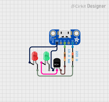
This circuit consists of a combination of resistors, LEDs, a transistor, and a USB breakout board. The circuit is designed to control the illumination of two LEDs (one red and one green) using an NPN transistor. The USB breakout board provides power and data connections.
Component List
Resistor (220 Ohms)
- Pins: pin1, pin2
- Description: Limits current to the red LED.
- Properties:
- Resistance: 220 Ohms
LED: Two Pin (green)
- Pins: cathode, anode
- Description: Green LED for visual indication.
Adafruit Micro USB Breakout
- Pins: GND, ID, D+, D-, VBUS
- Description: Provides power and data connections from a USB source.
LED: Two Pin (red)
- Pins: cathode, anode
- Description: Red LED for visual indication.
NPN-Transistor
- Pins: E (Emitter), C (Collector), B (Base)
- Description: Controls the current flow through the LEDs.
Resistor (10k Ohms)
- Pins: pin1, pin2
- Description: Limits current to the base of the transistor.
- Properties:
- Resistance: 10k Ohms
Wiring Details
Resistor (220 Ohms)
- pin1 is connected to VBUS of the Adafruit Micro USB Breakout.
- pin2 is connected to anode of the red LED.
LED: Two Pin (green)
- cathode is connected to C (Collector) of the NPN-Transistor.
- anode is not connected in this circuit.
Adafruit Micro USB Breakout
- GND is connected to E (Emitter) of the NPN-Transistor and cathode of the red LED.
- ID is not connected in this circuit.
- D+ is connected to pin1 of the 10k Ohms Resistor.
- D- is not connected in this circuit.
- VBUS is connected to pin1 of the 220 Ohms Resistor.
LED: Two Pin (red)
- cathode is connected to GND of the Adafruit Micro USB Breakout and E (Emitter) of the NPN-Transistor.
- anode is connected to pin2 of the 220 Ohms Resistor.
NPN-Transistor
- E (Emitter) is connected to GND of the Adafruit Micro USB Breakout and cathode of the red LED.
- C (Collector) is connected to cathode of the green LED.
- B (Base) is connected to pin2 of the 10k Ohms Resistor.
Resistor (10k Ohms)
- pin1 is connected to D+ of the Adafruit Micro USB Breakout.
- pin2 is connected to B (Base) of the NPN-Transistor.
Code
There is no microcontroller code provided for this circuit.