
Arduino Nano RFID Access Control with Servo and Buzzer Feedback
View and Edit Project In Cirkit Designer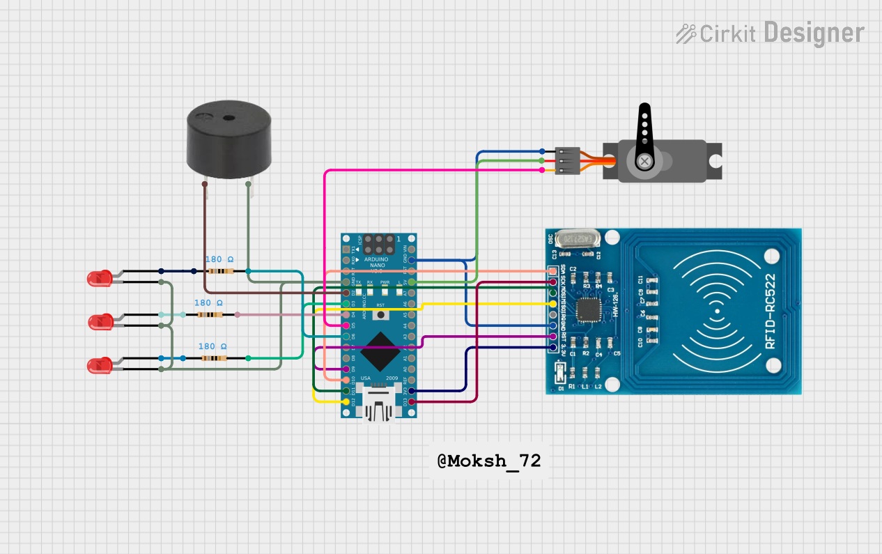
Circuit Documentation
Summary of the Circuit
This circuit is designed around an Arduino Nano microcontroller and includes a variety of components to perform specific functions. The circuit features an RFID-RC522 module for RFID reading, a servo motor for physical actuation, a buzzer for audio feedback, and three LEDs for visual indication of the system's status. The Arduino Nano controls these peripherals and communicates with the RFID reader via SPI protocol. The circuit is intended to read RFID tags, provide visual and auditory feedback, and actuate a servo motor based on the tag data.
Component List
Arduino Nano
- Microcontroller board based on the ATmega328P
- It has a variety of digital and analog I/O pins and supports serial communication protocols like SPI and UART.
LED: Two Pin (red)
- Simple red LEDs for visual indication
- Each LED has an anode and cathode for connection to the power supply and ground, respectively.
Resistor
- Three resistors with a resistance of 180 Ohms
- Used to limit current to the LEDs to prevent damage.
Servo
- A servo motor capable of precise angular positioning
- It has three pins: power (VCC), ground (GND), and control (PWM).
Buzzer
- An audio signaling device
- It has two pins: signal (PIN) and ground (GND).
RFID-RC522
- An RFID reader module for reading RFID tags
- It communicates with the Arduino Nano via SPI and has pins for power (VCC), ground (GND), reset (RST), and SPI communication (MISO, MOSI, SCK, SDA).
Wiring Details
Arduino Nano
- GND: Connected to the cathodes of all LEDs, the ground of the buzzer, the ground of the servo, and the ground of the RFID-RC522.
- D2: Connected to the buzzer signal pin.
- D3, D4, D6: Connected to the anodes of the LEDs through 180 Ohm resistors.
- D5: Connected to the PWM pin of the servo.
- D9: Connected to the RST pin of the RFID-RC522.
- D10: Connected to the SDA pin of the RFID-RC522.
- D11/MOSI: Connected to the MOSI pin of the RFID-RC522.
- D12/MISO: Connected to the MISO pin of the RFID-RC522.
- D13/SCK: Connected to the SCK pin of the RFID-RC522.
- 5V: Connected to the VCC pin of the servo.
- 3V3: Connected to the VCC (3.3V) pin of the RFID-RC522.
LED: Two Pin (red)
- Anode: Connected to the Arduino Nano through a 180 Ohm resistor on pins D3, D4, and D6.
- Cathode: Connected to the GND pin on the Arduino Nano.
Resistor
- Pin1: Connected to the anode of the corresponding LED.
- Pin2: Connected to the corresponding digital pin on the Arduino Nano (D3, D4, or D6).
Servo
- VCC: Connected to the 5V pin on the Arduino Nano.
- GND: Connected to the GND pin on the Arduino Nano.
- PWM: Connected to pin D5 on the Arduino Nano.
Buzzer
- PIN: Connected to pin D2 on the Arduino Nano.
- GND: Connected to the GND pin on the Arduino Nano.
RFID-RC522
- VCC (3.3V): Connected to the 3V3 pin on the Arduino Nano.
- RST: Connected to pin D9 on the Arduino Nano.
- GND: Connected to the GND pin on the Arduino Nano.
- IRQ: Not connected in this circuit.
- MISO: Connected to pin D12/MISO on the Arduino Nano.
- MOSI: Connected to pin D11/MOSI on the Arduino Nano.
- SCK: Connected to pin D13/SCK on the Arduino Nano.
- SDA: Connected to pin D10 on the Arduino Nano.
Documented Code
#include <SPI.h>
#include <MFRC522.h>
#include <Servo.h>

#define SS_PIN 10
#define RST_PIN 9
#define Buzzer 2  // Buzzer for feedback
#define LED1 3
#define LED2 4
#define LED3 6  // Red LED for wrong card indication

MFRC522 rfid(SS_PIN, RST_PIN);
Servo myServo;

byte led1 = 0;
byte led2 = 0;
bool cardRead = false;

void setup() {
  Serial.begin(9600);
  Serial.println("Please put your card..");
  SPI.begin();
  rfid.PCD_Init();
  pinMode(LED1, OUTPUT);
  pinMode(LED2, OUTPUT);
  pinMode(LED3, OUTPUT);  // Set the red LED pin as output
  pinMode(Buzzer, OUTPUT);  // Set the buzzer pin as output
  myServo.attach(5);  // Attach the servo to pin 5
  myServo.write(0);   // Set initial position to 0 degrees
}

void loop() {
  if (!rfid.PICC_IsNewCardPresent()) {
    cardRead = false;  // Reset the card read status when no new card is present
    digitalWrite(LED3, LOW);  // Turn off red LED if no card is present
    noTone(Buzzer);  // Ensure buzzer is off when no card is present
    return;
  }

  if (!rfid.PICC_ReadCardSerial()) {
    return;
  }

  // Check if a card is already read to prevent multiple reads
  if (cardRead) {
    return;  // Exit loop if the card has already been processed
  }

  cardRead = true;  // Set card as read
  Serial.print("NUID tag is :");
  String ID = "";
  for (byte i = 0; i < rfid.uid.size; i++) {
    Serial.print(rfid.uid.uidByte[i] < 0x10 ? " 0" : " ");
    Serial.print(rfid.uid.uidByte[i], HEX);
    ID.concat(String(rfid.uid.uidByte[i] < 0x10 ? " 0" : " "));
    ID.concat(String(rfid.uid.uidByte[i], HEX));
    delay(300);
  }
  Serial.println();
  ID.toUpperCase();

  // Condition for LED1 user
  if ((ID.substring(1) == "79 EB 83 71" || ID.substring(1) == "47 BF 53 3B" || ID.substring(1) == "E9 DF 62 59") && led1 == 0 && led2 == 0) {
    digitalWrite(LED1, HIGH);
    Serial.println("LED1 is ON..");
    led1 = 1;
    tone(Buzzer, 1000, 200);  // Buzzer on for 200ms as feedback
    myServo.write(180);  // Move servo to 180 degrees
  } else if ((ID.substring(1) == "79 EB 83 71" || ID.substring(1) == "47 BF 53 3B" || ID.substring(1) == "E9 DF 62 59") && led1 == 1) {
    digitalWrite(LED1, LOW);
    Serial.println("LED1 is OFF..");
    led1 = 0;
    tone(Buzzer, 1000, 200);  // Buzzer on for 200ms as feedback
    myServo.write(0);  // Return servo to 0 degrees
  }
  // Condition for LED2 user
  else if ((ID.substring(1) == "E7 7A AE 60" || ID.substring(1) == "01 02 03 04") && led2 == 0 && led1 == 0) {
    digitalWrite(LED2, HIGH);
    Serial.println("LED2 is ON..");
    led2 = 1;
    tone(Buzzer, 1000, 200);  // Buzzer on for 200ms as feedback
    myServo.write(180);  // Move servo to 180 degrees
  } else if ((ID.substring(1) == "E7 7A AE 60" || ID.substring(1) == "01 02 03 04") && led2 == 1) {
    digitalWrite(LED2, LOW);
    Serial.println("LED2 is OFF..");
    led2 = 0;
    tone(Buzzer, 1000, 200);  // Buzzer on for 200ms as feedback
    myServo.write(0);  // Return servo to 0 degrees
  }
  // Error feedback for wrong card or when access is restricted
  else {
    Serial.println("Access denied! Please put the correct card or wait until the other user exits.");
    digitalWrite(LED3, HIGH);  // Turn on red LED if the card is wrong or access is denied
    tone(Buzzer, 500, 1000);   // Buzzer on for 1 second with a lower tone as error feedback
    delay(1000);
    digitalWrite(LED3, LOW);   // Turn off the red LED after the delay
    noTone(Buzzer);            // Ensure the buzzer is turned off