
Arduino Mega 2560-Based Weather Station with LCD Display and DHT11 Sensor
View and Edit Project In Cirkit Designer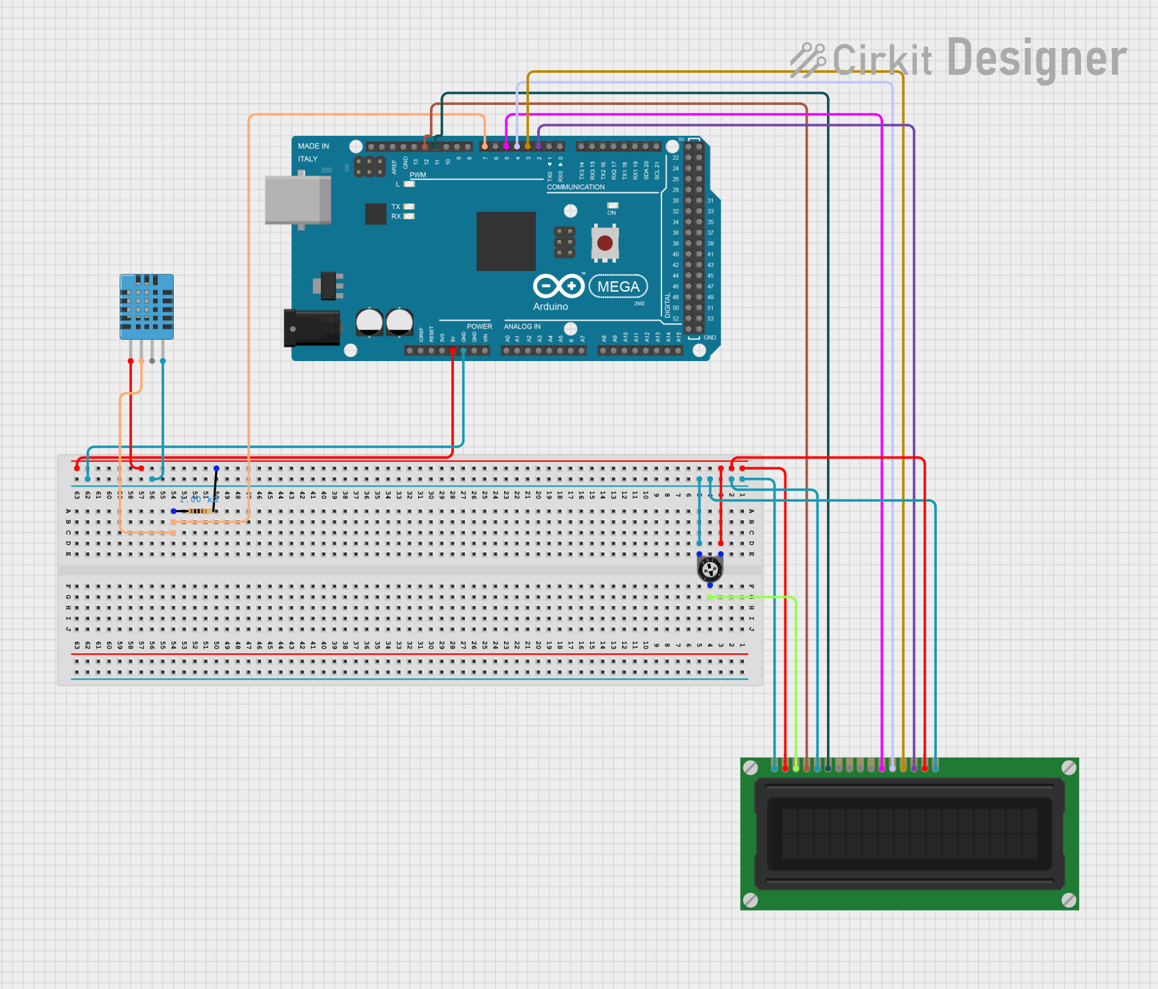
Circuit Documentation
Summary
This circuit involves an Arduino Mega 2560 microcontroller interfacing with an LCD Display, a DHT11 Humidity and Temperature Sensor, a Trimmer Potentiometer, and a Resistor. The Arduino Mega 2560 controls the LCD Display and reads data from the DHT11 sensor. The Trimmer Potentiometer is used to adjust the contrast of the LCD Display.
Component List
LCD Display (16 pin)
- Description: A 16-pin LCD display used to show alphanumeric characters.
- Pins: VSS, VDD, VO, RS, R_W, E, DB0, DB1, DB2, DB3, DB4, DB5, DB6, DB7, A, K
Trimmer Potentiometer
- Description: A variable resistor used to adjust the contrast of the LCD Display.
- Pins: leg1, wiper, leg2
- Properties:
- Resistance: 10000 Ohms
DHT11 Humidity and Temperature Sensor
- Description: A sensor used to measure humidity and temperature.
- Pins: VDD, DATA, NULL, GND
Arduino Mega 2560
- Description: A microcontroller board based on the ATmega2560.
- Pins: IOREF, RESET, 3V3, 5V, GND, VIN, A0-A15, D0-D53, SDA, SCL, AREF
Resistor
- Description: A resistor used in the circuit.
- Pins: pin1, pin2
- Properties:
- Resistance: 1000 Ohms
Wiring Details
LCD Display (16 pin)
- VSS: Connected to GND
- VDD: Connected to 5V
- VO: Connected to wiper of Trimmer Potentiometer
- RS: Connected to D12 PWM of Arduino Mega 2560
- R_W: Connected to GND
- E: Connected to D11 PWM of Arduino Mega 2560
- DB4: Connected to D5 PWM of Arduino Mega 2560
- DB5: Connected to D4 PWM of Arduino Mega 2560
- DB6: Connected to D3 PWM of Arduino Mega 2560
- DB7: Connected to D2 PWM of Arduino Mega 2560
- A: Connected to 5V
- K: Connected to GND
Trimmer Potentiometer
- leg1: Connected to 5V
- wiper: Connected to VO of LCD Display
- leg2: Connected to GND
DHT11 Humidity and Temperature Sensor
- VDD: Connected to 5V
- DATA: Connected to pin1 of Resistor and D7 PWM of Arduino Mega 2560
- GND: Connected to GND
Arduino Mega 2560
- 5V: Connected to VDD of LCD Display, VDD of DHT11 Sensor, leg1 of Trimmer Potentiometer
- GND: Connected to VSS, R_W, K of LCD Display, GND of DHT11 Sensor, leg2 of Trimmer Potentiometer
- D12 PWM: Connected to RS of LCD Display
- D11 PWM: Connected to E of LCD Display
- D5 PWM: Connected to DB4 of LCD Display
- D4 PWM: Connected to DB5 of LCD Display
- D3 PWM: Connected to DB6 of LCD Display
- D2 PWM: Connected to DB7 of LCD Display
- D7 PWM: Connected to DATA of DHT11 Sensor
Resistor
- pin1: Connected to DATA of DHT11 Sensor and D7 PWM of Arduino Mega 2560
- pin2: Connected to VDD of LCD Display
Documented Code
Arduino Mega 2560 Code
void setup() {
  // put your setup code here, to run once:

}

void loop() {
  // put your main code here, to run repeatedly:

}
Additional Documentation
// This file is intended for additional documentation purposes.