
Circuit Documentation
Summary
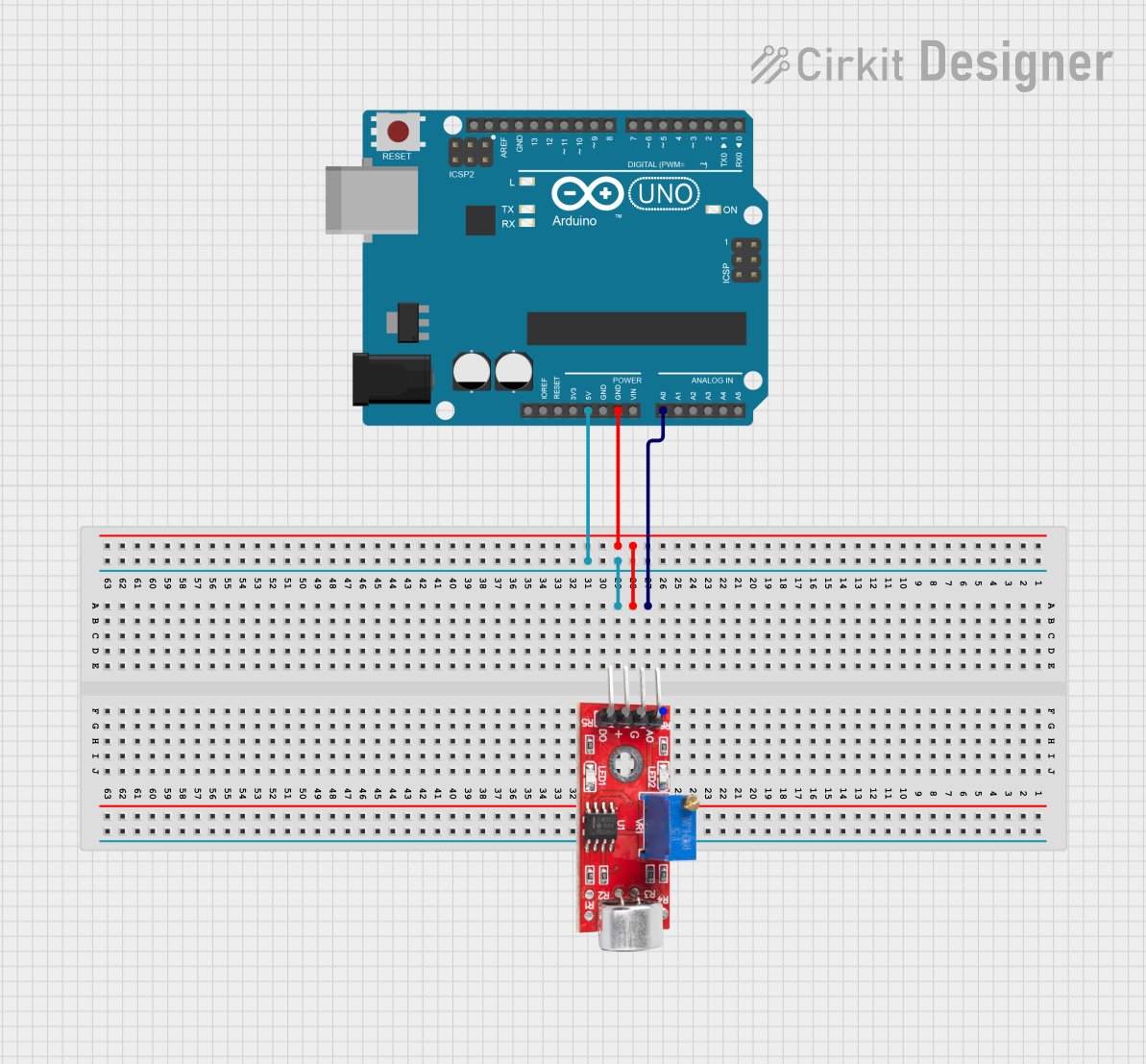
This document provides a detailed overview of a simple circuit consisting of an Arduino UNO microcontroller and a Sound Sensor. The Arduino UNO is used to read data from the Sound Sensor. The circuit is powered by the 5V supply from the Arduino UNO, and the ground connections are shared among the components.
Component List
Arduino UNO
- Description: A microcontroller board based on the ATmega328P.
- Pins: UNUSED, IOREF, Reset, 3.3V, 5V, GND, Vin, A0, A1, A2, A3, A4, A5, SCL, SDA, AREF, D13, D12, D11, D10, D9, D8, D7, D6, D5, D4, D3, D2, D1, D0
- Purpose in Circuit: Acts as the main controller to read data from the Sound Sensor and process it.
Sound Sensor
- Description: A sensor module used to detect sound levels.
- Pins: Analog, GND, VCC, Digital
- Purpose in Circuit: Detects sound levels and sends the data to the Arduino UNO for processing.
Wiring Details
Arduino UNO
- A0: Connected to the Analog pin of the Sound Sensor.
- GND: Connected to the GND pin of the Sound Sensor.
- 5V: Connected to the VCC pin of the Sound Sensor.
Sound Sensor
- Analog: Connected to the A0 pin of the Arduino UNO.
- GND: Connected to the GND pin of the Arduino UNO.
- VCC: Connected to the 5V pin of the Arduino UNO.
- Digital: Not connected in this circuit.
Documented Code
Arduino UNO Code (sketch.ino)
void setup() {
  // put your setup code here, to run once:

}

void loop() {
  // put your main code here, to run repeatedly:

}
This code is a basic template for the Arduino UNO. The setup() function is where you initialize any settings or configurations, and the loop() function is where the main code runs repeatedly. In this circuit, you would typically add code to read the analog value from the Sound Sensor and process it accordingly.
Additional Documentation (documentation.txt)
This file is currently empty and can be used to add any additional notes or documentation related to the project.