
ESP32-Controlled Self-Balancing Robot with MPU-6050 and L298N Motor Driver
View and Edit Project In Cirkit Designer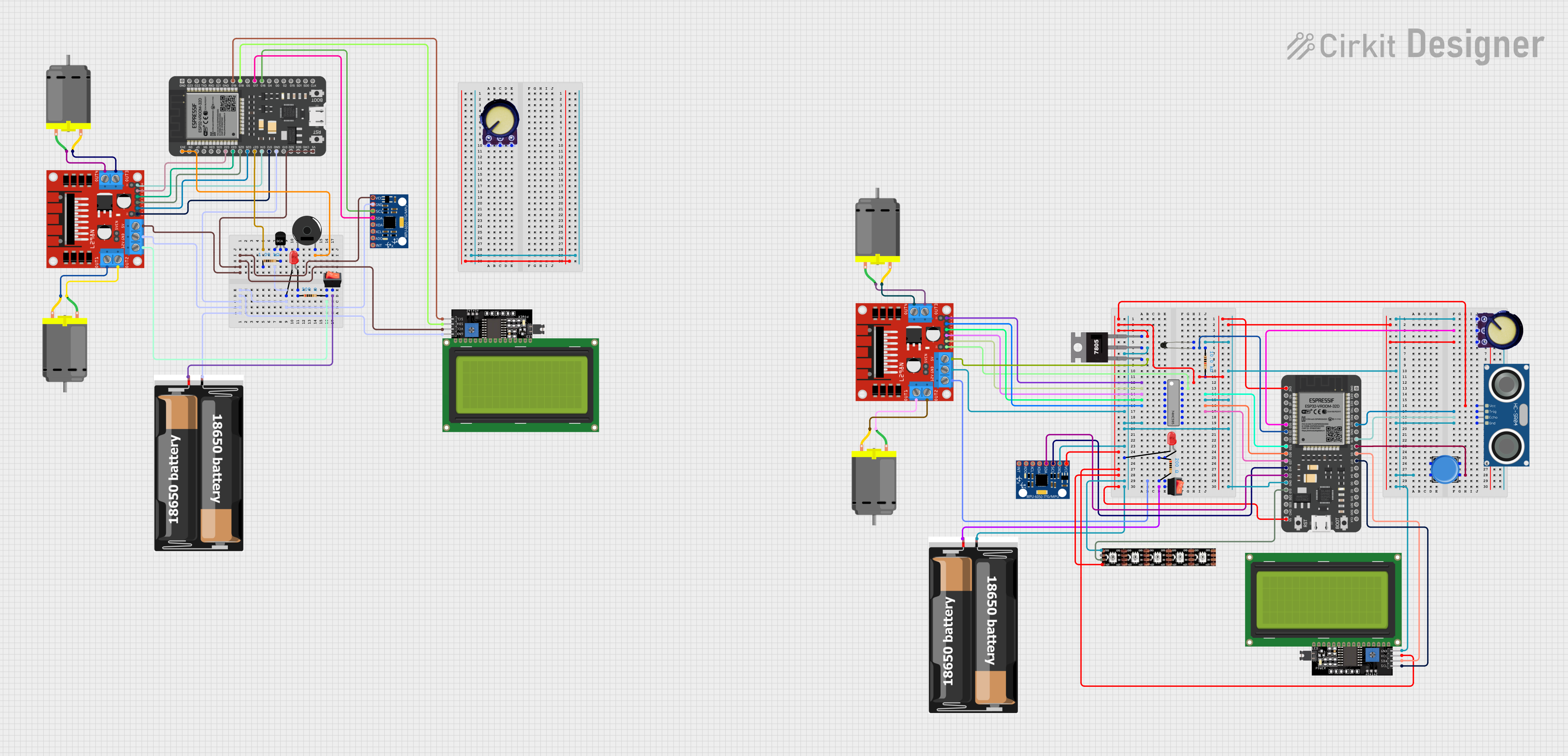
Circuit Documentation
Summary
The circuit in question is designed to control a two-wheeled self-balancing robot. It utilizes an ESP32 microcontroller to read tilt angles from an MPU-6050 sensor and adjust the speed of two DC motors via an L298N motor driver to maintain balance. The circuit also includes a 2x 18650 battery pack for power, a piezo buzzer for audio feedback, various resistors for current limiting and pull-up/pull-down functions, a potentiometer for adjustable parameters, an NPN transistor for switching, a rocker switch for power control, LEDs for visual feedback, an LCD display for user interface, an HC-SR04 ultrasonic sensor for distance measurement, a WS2815 LED strip for lighting effects, an NTC thermistor for temperature sensing, and a 74HC595 shift register for expanding output pins. A 7805 voltage regulator is used to provide a stable 5V supply to certain components.
Component List
Active Components
- ESP32 - 38 pins: A microcontroller with WiFi and Bluetooth capabilities, used as the main processing unit.
- L298N DC motor driver: A dual H-bridge motor driver for controlling the speed and direction of two DC motors.
- MPU-6050: A 6-axis gyroscope and accelerometer module for detecting the tilt angle of the robot.
- LCD Display 20x4 I2C: An alphanumeric liquid crystal display with an I2C interface for displaying information.
- Piezo Buzzer: An electronic device that emits sound when voltage is applied.
- NPN-Transistor: A bipolar junction transistor used for switching or amplification.
- 74HC595: An 8-bit shift register with output latches for expanding digital outputs.
- HC-SR04 Ultrasonic Sensor: A sensor for measuring distances using ultrasonic waves.
- WS2815 LED Strip: An addressable LED strip that can display multiple colors and patterns.
Passive Components
- Resistor (1k Ohms, 200 Ohms, 10k Ohms): Resistors used for current limiting and voltage division.
- Potentiometer: A variable resistor used to adjust a voltage signal.
- LED: Two Pin (red): A light-emitting diode that emits red light when forward-biased.
- NTC (Thermistor): A temperature-sensitive resistor whose resistance changes with temperature.
- 2x 18650 Battery Pack: A power source composed of two 18650 lithium-ion batteries.
Electromechanical Components
- DC Motor: An electric motor that runs on direct current (DC) electricity.
- Rocker Switch: A switch for turning the power supply on and off.
Wiring Details
ESP32 - 38 pins
GNDconnected to the common ground net.5Vconnected to the 5V power net.3V3connected to the 3.3V power net.G12,G14,G25,G26,G32,G33,G35,G18,G19,G21,G5,G13,G16,G17connected to various components for control signals.
L298N DC motor driver
GNDconnected to the common ground net.5Vconnected to the 5V power net.12Vconnected to the 12V power net from the battery pack through a rocker switch.ENA,ENB,IN1,IN2,IN3,IN4connected to the ESP32 for motor control.OUT1,OUT2,OUT3,OUT4connected to the DC motors.
MPU-6050
GNDconnected to the common ground net.VCCconnected to the 3.3V power net.SCL,SDAconnected to the ESP32 for I2C communication.
LCD Display 20x4 I2C
GNDconnected to the common ground net.VCCconnected to the 5V power net.SCL,SDAconnected to the ESP32 for I2C communication.
Piezo Buzzer
- One pin connected to the 3.3V power net.
- The other pin connected to the common ground net.
NPN-Transistor
E(Emitter) connected to the common ground net.C(Collector) connected to the cathode of the LED through a resistor.B(Base) connected to a GPIO pin on the ESP32 through a resistor.
74HC595
GNDconnected to the common ground net.VCCconnected to the 5V power net.Q0-Q7connected to various components for control signals.DS (DATA),OE (Enable),ST_CP (RCLK),SH_CP (SRCLK)connected to the ESP32 for serial data input and control.
HC-SR04 Ultrasonic Sensor
GNDconnected to the common ground net.VCCconnected to the 5V power net.TRIG,ECHOconnected to the ESP32 for triggering and echo reading.
WS2815 LED Strip
GNDconnected to the common ground net.+12Vconnected to the 12V power net.D0connected to a GPIO pin on the ESP32 for data control.
NTC (Thermistor)
- One pin connected to the 3.3V power net through a resistor.
- The other pin connected to a GPIO pin on the ESP32 for analog reading.
2x 18650 Battery Pack
gndconnected to the common ground net.vccconnected to the power net, providing 12V to the circuit.
DC Motor
- Two pins connected to the
OUT1,OUT2,OUT3,OUT4of the L298N motor driver.
Rocker Switch
inputconnected to thevccof the battery pack.outputconnected to the12Vinput of the L298N motor driver and theVinof the 7805 voltage regulator.
Resistor (1k Ohms, 200 Ohms, 10k Ohms)
- Connected in various places for current limiting and pull-up/pull-down functions.
Potentiometer
GNDandVCCconnected to the common ground and power nets, respectively.Outputconnected to a GPIO pin on the ESP32 for analog input.
LED: Two Pin (red)
cathodeconnected to the common ground net or the collector of the NPN transistor.anodeconnected to the 3.3V power net through a resistor.
7805 Voltage Regulator
Vinconnected to the 12V power net.Gndconnected to the common ground net.Voutconnected to the 5V power net.
Documented Code
ESP32 Microcontroller Code (Instance 1)
/*
 * Arduino Sketch for a Two-Wheeled Self-Balancing Robot
 *
 * This code uses an MPU-6050 to detect the tilt angle of the robot and controls
 * two DC motors via an L298N motor driver to keep the robot upright. The ESP32
 * microcontroller reads the angle from the MPU-6050 and adjusts the motor speeds
 * accordingly to balance the robot.
 */

#include <Wire.h>
#include <MPU6050.h>

MPU6050 mpu;

// Motor driver pins
const int ENA = 12;
const int ENB = 14;
const int IN1 = 26;
const int IN2 = 25;
const int IN3 = 33;
const int IN4 = 32;

// PID constants
float Kp = 2.0;
float Ki = 5.0;
float Kd = 1.0;

float setPoint = 0.0;
float input, output;
float errSum, lastErr;

void setup() {
  Serial.begin(115200);
  Wire.begin();
  mpu.initialize();
  if (!mpu.testConnection()) {
    Serial.println("MPU6050 connection failed");
    while (1);
  }
  pinMode(ENA, OUTPUT);
  pinMode(ENB, OUTPUT);
  pinMode(IN1, OUTPUT);
  pinMode(IN2, OUTPUT);
  pinMode(IN3, OUTPUT);
  pinMode(IN4, OUTPUT);
}

void loop() {
  int16_t ax, ay, az;
  int16_t gx, gy, gz;
  mpu.getMotion6(&ax, &ay, &az, &gx, &gy, &gz);
  float angle = atan2(ay, az) * 180 / PI;
  input = angle;
  float error = setPoint - input;
  errSum += (error * Ki);
  float dErr = (error - lastErr) * Kd;
  output = Kp * error + errSum + dErr;
  lastErr = error;
  setMotorSpeed(output);
  delay(10