Arduino Mega 2560 Controlled Quadruped Robot with Bluetooth Voice Commands

Circuit Documentation
Summary
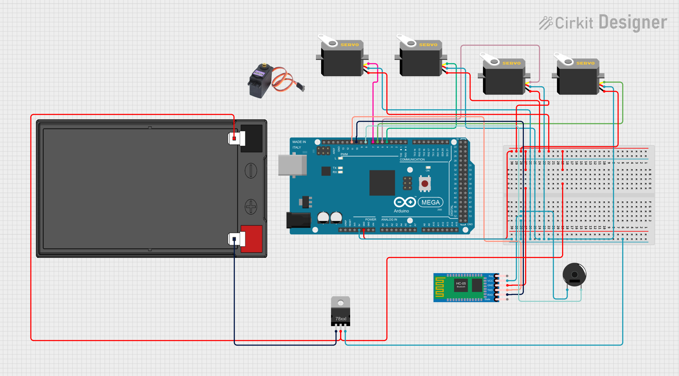
The circuit in question is designed to control multiple servo motors via an Arduino Mega 2560, which receives commands through a Bluetooth module (HC-05). The circuit also includes a piezo buzzer for audio feedback and is powered by a 12V 7Ah battery, with a voltage regulator to provide the necessary 5V to the components. The servos are controlled by PWM signals from the Arduino, and the Bluetooth module facilitates wireless communication.
Component List
Arduino Mega 2560
- Microcontroller board based on the ATmega2560
- It has 54 digital input/output pins (of which 15 can be used as PWM outputs), 16 analog inputs, 4 UARTs (hardware serial ports), a 16 MHz crystal oscillator, a USB connection, a power jack, an ICSP header, and a reset button.
Servo Motors
- Four generic servo motors are used for actuation.
- Each servo has three connections: ground (GND), power (VCC), and control signal (Pulse).
HC-05 Bluetooth Module
- A Bluetooth module for wireless communication.
- It has six pins: Key, VCC, TXD, RXD, State, and GND.
Piezo Buzzer
- An electronic device that produces sound when voltage is applied.
- It has two pins: pin 1 and pin 2.
MG996R
- A high-torque digital servo motor.
- It has three pins: GND, VCC, and SIG.
12v 7ah Battery
- A rechargeable battery providing the power source for the circuit.
- It has two terminals: 12v + and 12v -.
Voltage Regulator
- A device that maintains a constant voltage level.
- It has three pins: IN, GND, and OUT.
Wiring Details
Arduino Mega 2560
- 5V pin is connected to the 5V power rail.
- GND pin is connected to the ground rail.
- Digital pins D4, D5, D6, and D7 are connected to the control signal (Pulse) pins of the four servo motors.
- Digital pins D10 and D11 are connected to the RXD and TXD pins of the HC-05 Bluetooth Module, respectively.
- Digital pin D8 is connected to pin 2 of the Piezo Buzzer.
Servo Motors
- VCC pins are connected to the 5V power rail.
- GND pins are connected to the ground rail.
- Pulse pins are connected to the corresponding PWM pins on the Arduino Mega 2560.
HC-05 Bluetooth Module
- VCC pin is connected to the 5V power rail.
- GND pin is connected to the ground rail.
- TXD pin is connected to Digital pin D10 on the Arduino Mega 2560.
- RXD pin is connected to Digital pin D11 on the Arduino Mega 2560.
Piezo Buzzer
- Pin 1 is connected to the 5V power rail.
- Pin 2 is connected to Digital pin D8 on the Arduino Mega 2560.
12v 7ah Battery
- 12v + terminal is connected to the IN pin of the Voltage Regulator.
- 12v - terminal is connected to the ground rail.
Voltage Regulator
- IN pin is connected to the 12v + terminal of the 12v 7ah Battery.
- GND pin is connected to the ground rail.
- OUT pin is connected to the 5V power rail.
Documented Code
#include <Servo.h>
#include <SoftwareSerial.h>

// Create servo objects to control each leg
Servo frontLeftLeg;
Servo frontRightLeg;
Servo backLeftLeg;
Servo backRightLeg;

// Set up the Bluetooth communication
SoftwareSerial bluetoothSerial(10, 11); // RX, TX

void setup() {
  // Attach the servos to the servo objects
  frontLeftLeg.attach(4);  // D4 PWM
  frontRightLeg.attach(5); // D5 PWM
  backLeftLeg.attach(6);   // D6 PWM
  backRightLeg.attach(7);  // D7 PWM

  // Start the Bluetooth communication
  bluetoothSerial.begin(9600);
}

void loop() {
  if (bluetoothSerial.available()) {
    String voiceCommand = bluetoothSerial.readString();

    if (voiceCommand == "raise front left") {
      frontLeftLeg.write(45);
    } else if (voiceCommand == "lower front left") {
      frontLeftLeg.write(90);
    } else if (voiceCommand == "move forward") {
      frontLeftLeg.write(30);
      backRightLeg.write(30);
      delay(500);

      // Step 2: Move front right and back left legs to starting position
      frontRightLeg.write(90);
      backLeftLeg.write(90);
      delay(500);

      // Step 3: Move front right and back left legs forward
      frontRightLeg.write(30);
      backLeftLeg.write(30);
      delay(500);

      // Step 4: Move front left and back right legs to starting position
      frontLeftLeg.write(90);
      backRightLeg.write(90);
      delay(500);
    }
    // Add more conditions for other voice commands and servo movements
  }
}
This code is designed to be uploaded to the Arduino Mega 2560. It initializes four servo objects and a software serial for Bluetooth communication. In the setup() function, the servos are attached to their respective pins, and the Bluetooth module is initialized. The loop() function listens for incoming Bluetooth data and moves the servos based on the received voice commands.