Arduino-Controlled Light-Sensitive LED Circuit
Circuit Documentation
Summary
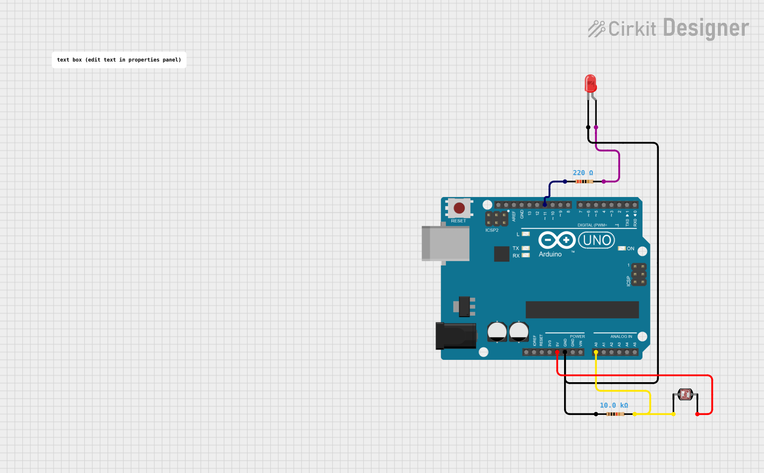
This circuit is designed to measure light intensity using a photocell (Light Dependent Resistor, LDR) and adjust the brightness of an LED accordingly. The photocell forms part of a voltage divider network connected to the Arduino UNO's analog input. The LED's brightness is inversely proportional to the light level detected by the photocell, meaning the LED gets brighter as the light level decreases. The Arduino UNO controls the LED brightness through PWM on a digital pin.
Component List
Resistor (10k Ohms)
- Description: A resistor with a resistance of 10,000 Ohms.
- Purpose: Part of the voltage divider with the photocell to measure light intensity.
Resistor (220 Ohms)
- Description: A resistor with a resistance of 220 Ohms.
- Purpose: Current-limiting resistor for the LED to prevent it from drawing too much current.
Photocell (LDR)
- Description: A light-dependent resistor whose resistance changes with light intensity.
- Purpose: To sense the ambient light level.
Arduino UNO
- Description: A microcontroller board based on the ATmega328P.
- Purpose: To read the analog value from the photocell and adjust the LED brightness accordingly.
LED: Two Pin (red)
- Description: A red light-emitting diode.
- Purpose: To provide a visual indication of the light level detected by the photocell.
Comment
- Description: A placeholder or annotation.
- Purpose: To add comments or notes within the circuit, not an actual physical component.
Wiring Details
Resistor (10k Ohms)
- One end connected to the Arduino UNO's analog input A0.
- The other end connected to the Arduino UNO's GND.
Resistor (220 Ohms)
- One end connected to the Arduino UNO's digital pin D11.
- The other end connected to the anode of the LED.
Photocell (LDR)
- One end connected to the Arduino UNO's 5V.
- The other end connected to the Arduino UNO's analog input A0.
Arduino UNO
- 5V and GND pins used to power the photocell and LED circuit.
- Analog input A0 reads the voltage across the photocell.
- Digital pin D11 controls the LED brightness through PWM.
LED: Two Pin (red)
- Anode connected to digital pin D11 through a 220 Ohm resistor.
- Cathode connected to the Arduino UNO's GND.
Documented Code
/*
  Photocell Light Sensitivity Tester

  This sketch is designed to read the light level from a photocell (also known as a photoresistor or LDR) and adjust
  the brightness of an LED accordingly.
  The photocell is part of a voltage divider connected to analog input A0, with a 10K resistor connecting to ground.
  The LED is connected to digital pin 11 through a current-limiting resistor.
  As the light level decreases, the LED brightness increases.

  Circuit connections:
  - Photocell one end connected to 5V
  - Photocell other end connected to A0
  - 10K resistor from A0 to GND
  - LED anode connected to pin 11 through a resistor
  - LED cathode connected to GND
*/

int photocellPin = A0; // the cell and 10K pulldown are connected to A0
int photocellReading;   // the analog reading from the sensor divider
int LEDpin = 11;        // connect Red LED to pin 11 (PWM pin)
int LEDbrightness;      // variable to store the brightness value

void setup() {
  Serial.begin(9600); // Start serial communication for debugging
}

void loop() {
  photocellReading = analogRead(photocellPin); // read the value from the sensor

  Serial.print("Analog reading = ");
  Serial.println(photocellReading); // print the raw analog reading

  // Invert the reading since the LED gets brighter in darkness
  photocellReading = 1023 - photocellReading;

  // Map the reading to the PWM range (0-255) and set LED brightness
  LEDbrightness = map(photocellReading, 0, 1023, 0, 255);
  analogWrite(LEDpin, LEDbrightness);

  delay(100); // Wait for 100 milliseconds before the next loop
}
This code is designed to run on the Arduino UNO microcontroller. It initializes the serial communication for debugging purposes, reads the analog value from the photocell, inverts the reading to increase LED brightness as it gets darker, maps the reading to a PWM value, and writes this value to the LED pin to adjust its brightness.