ESP32-Controlled Dual DC Motor Driver with H-Bridge

Circuit Documentation
Summary
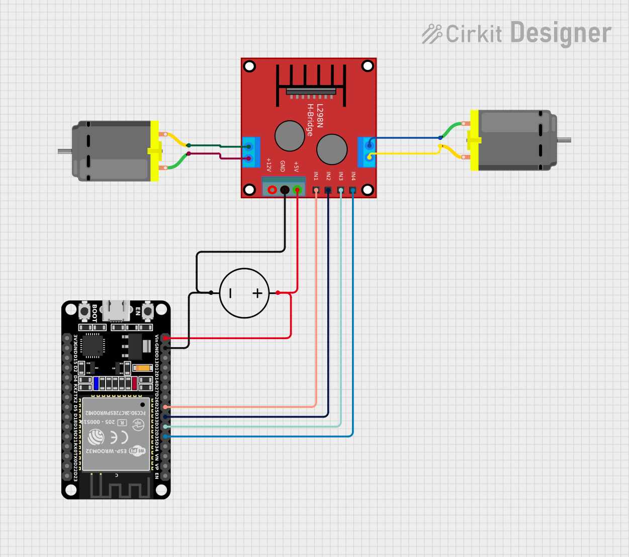
The circuit in question is designed to control two DC motors using an ESP32 microcontroller and an H-bridge motor driver (often referred to as a "ponte h"). The ESP32 is responsible for sending control signals to the H-bridge, which in turn drives the motors. The power for the circuit is supplied by a DC power source, which provides the necessary voltage to the ESP32 and the H-bridge. The ground from the power source is shared across the ESP32 and the H-bridge to complete the circuit.
Component List
ESP32 (30 pin)
- Description: A microcontroller with WiFi and Bluetooth capabilities, featuring a wide range of GPIO pins.
- Pins: EN, VP, VN, D34, D35, D32, D33, D25, D26, D27, D14, D12, D13, GND, Vin, D23, D22, TX0, RX0, D21, D19, D18, D5, TX2, RX2, D4, D2, D15, 3V3
Ponte H (H-bridge)
- Description: An electronic circuit that enables a voltage to be applied across a load in either direction. Commonly used for controlling the direction of DC motors.
- Pins: OUT4-Motor2, OUT3-Motor2, OUT2-Motor1, OUT1-Motor1, 5V, GND, 12V, IN3, IN1, IN2, IN4
DC Motor
- Description: An electric motor that runs on direct current (DC) electricity.
- Pins: pin 1, pin 2
DC Power Source
- Description: Provides the electrical energy required to power the circuit.
- Pins: Ground, Positive
Wiring Details
ESP32 (30 pin)
- D35: Connected to IN4 on the H-bridge
- D32: Connected to IN3 on the H-bridge
- D33: Connected to IN2 on the H-bridge
- D25: Connected to IN1 on the H-bridge
- GND: Shared ground with the H-bridge and DC Power Source
- Vin: Connected to the Positive pin of the DC Power Source
Ponte H (H-bridge)
- IN4: Controlled by D35 on the ESP32
- IN3: Controlled by D32 on the ESP32
- IN2: Controlled by D33 on the ESP32
- IN1: Controlled by D25 on the ESP32
- GND: Shared ground with the ESP32 and DC Power Source
- 5V: Connected to the Positive pin of the DC Power Source
- OUT4-Motor2: Connected to pin 1 of one DC Motor
- OUT3-Motor2: Connected to pin 2 of the same DC Motor
- OUT2-Motor1: Connected to pin 2 of the other DC Motor
- OUT1-Motor1: Connected to pin 1 of the other DC Motor
DC Motor (Motor 1)
- pin 1: Connected to OUT1-Motor1 on the H-bridge
- pin 2: Connected to OUT2-Motor1 on the H-bridge
DC Motor (Motor 2)
- pin 1: Connected to OUT4-Motor2 on the H-bridge
- pin 2: Connected to OUT3-Motor2 on the H-bridge
DC Power Source
- Ground: Shared ground with the ESP32 and H-bridge
- Positive: Connected to Vin on the ESP32 and 5V on the H-bridge
Documented Code
No code was provided for the microcontroller. The documentation of the code would typically include a description of the functionality, setup, and main loop, along with any functions or libraries used. Since no code is available, this section cannot be completed. If code becomes available, it should be documented here with comments explaining the purpose and functionality of each section of the code.