Cirkit Designer
Your all-in-one circuit design IDE
Home /
Project Documentation
Arduino UNO Based Heart Rate Monitor with OLED Display
Circuit Documentation
Summary
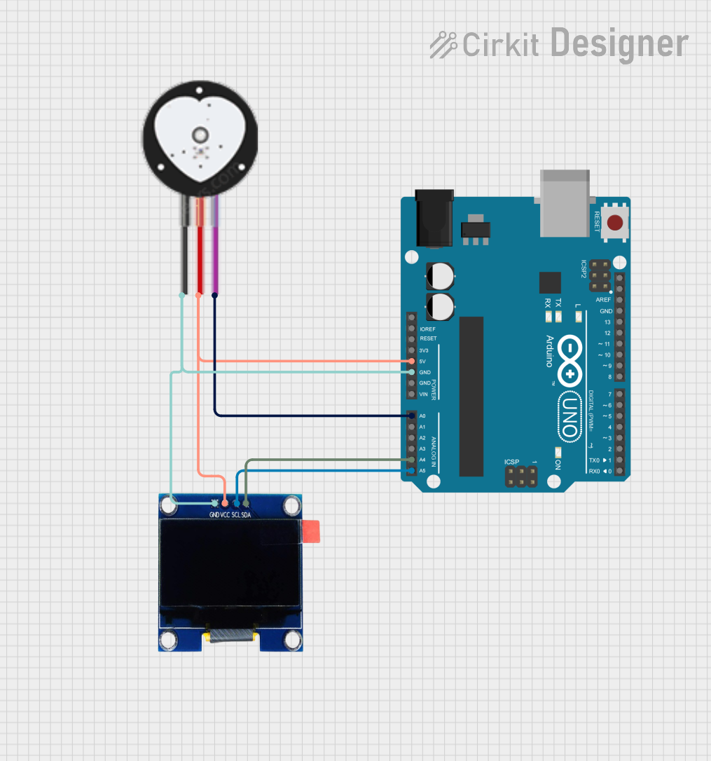
This circuit integrates an Arduino UNO microcontroller with a Heart Pulse Sensor and an OLED 1.3" display. The purpose of the circuit is to read the heart pulse signal from the sensor, process it with the Arduino, and display the beats per minute (BPM) on the OLED screen. The Arduino UNO is programmed to read analog values from the Heart Pulse Sensor, calculate the BPM, and display the results in real-time on the OLED display.
Component List
Arduino UNO
- Description: A microcontroller board based on the ATmega328P.
- Pins Used: IOREF, Reset, 3.3V, 5V, GND, Vin, A0, A4, A5, SCL, SDA.
Heart Pulse Sensor
- Description: A sensor that measures the heartbeat by detecting the pulse from a fingertip.
- Pins Used: GND, VCC, SIGNAL.
OLED 1.3"
- Description: A small display for showing data such as text and graphics.
- Pins Used: GND, VCC, SCL, SDA.
Wiring Details
Arduino UNO
- 5V connected to Heart Pulse Sensor VCC and OLED 1.3" VCC.
- GND connected to Heart Pulse Sensor GND and OLED 1.3" GND.
- A0 connected to Heart Pulse Sensor SIGNAL.
- A4 (SDA) connected to OLED 1.3" SDA.
- A5 (SCL) connected to OLED 1.3" SCL.
Heart Pulse Sensor
- VCC connected to Arduino UNO 5V.
- GND connected to Arduino UNO GND.
- SIGNAL connected to Arduino UNO A0.
OLED 1.3"
- VCC connected to Arduino UNO 5V.
- GND connected to Arduino UNO GND.
- SCL connected to Arduino UNO A5.
- SDA connected to Arduino UNO A4.
Documented Code
/*Heart pulse sensor with Arduino
 * https://srituhobby.com
 */

#include <SPI.h>
#include <Wire.h>
#include <Adafruit_GFX.h>
#include <Adafruit_SSD1306.h>

Adafruit_SSD1306 srituhobby = Adafruit_SSD1306(128, 64, &Wire);

#define sensor A0
#define Highpulse 540

int sX = 0;
int sY = 60;
int x = 0;
int Svalue;
int value;
long Stime = 0;
long Ltime = 0;
int count = 0;
int Bpm = 0;

void setup() {
  Serial.begin(9600);
  srituhobby.begin(SSD1306_SWITCHCAPVCC, 0x3C); // Address 0x3C for 128x32
  delay(1000);
  srituhobby.clearDisplay();
}

void loop() {
  Svalue = analogRead(sensor);
  Serial.println(Svalue);
  value = map(Svalue, 0, 1024, 0, 45);

  int y = 60 - value;

  if (x > 128) {
    x = 0;
    sX = 0;
    srituhobby.clearDisplay();
  }

  srituhobby.drawLine(sX, sY, x, y, WHITE);
  sX = x;
  sY = y;
  x ++;

  BPM();

  srituhobby.setCursor(0, 0);
  srituhobby.setTextSize(2);
  srituhobby.setTextColor(SSD1306_WHITE);
  srituhobby.print("BPM :");
  srituhobby.display();
}

void BPM() {

  if (Svalue > Highpulse) {
    Stime = millis() - Ltime;
    count++;

    if (Stime / 1000 >= 60) {
      Ltime = millis();
      Serial.println(count);
      srituhobby.setCursor(60, 0);
      srituhobby.setTextSize(2);
      srituhobby.setTextColor(SSD1306_WHITE);
      srituhobby.print(count);
      srituhobby.print("   ");
      srituhobby.display();
      count = 0;
    }
  }
}
Code Explanation
- Libraries: The code includes libraries for SPI, Wire, Adafruit_GFX, and Adafruit_SSD1306 to handle communication and display functions.
- Display Initialization: An Adafruit_SSD1306 object is created to manage the OLED display.
- Sensor Pin Definition: The analog pin A0 is defined as the input from the Heart Pulse Sensor.
- Variables: Several variables are declared to manage the sensor data and display coordinates.
- Setup Function: Initializes serial communication and the display, and clears the display.
- Loop Function: Reads the sensor value, maps it to a display range, draws the pulse waveform, and updates the BPM value on the display.
- BPM Function: Calculates the BPM based on the time between detected pulses and updates the display with the BPM value.