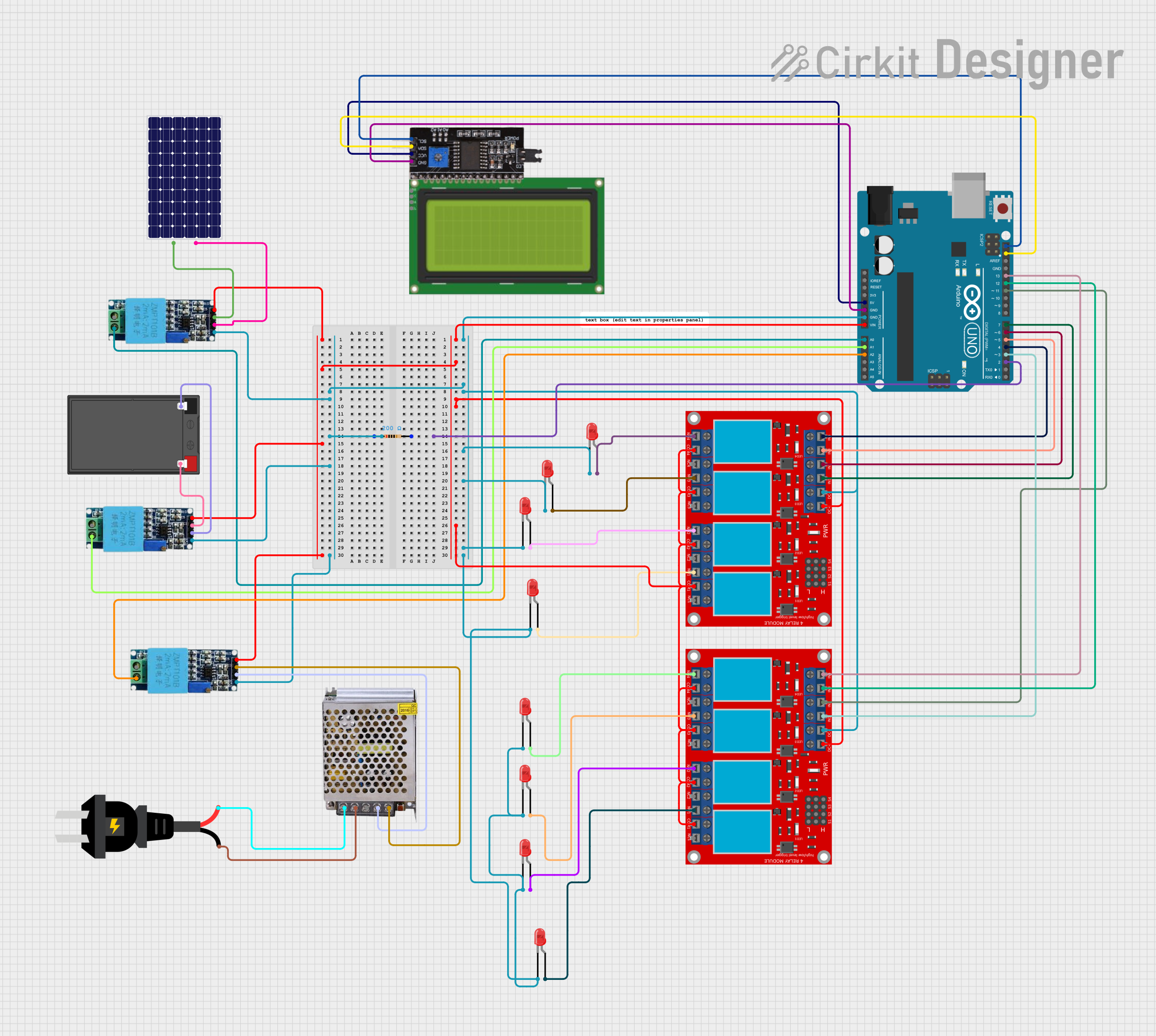
Arduino UNO Based Hybrid Energy Management System with I2C LCD Display and Relay Control

Circuit Documentation
Summary
The circuit is designed to manage a hybrid energy system that utilizes solar panels, a battery, and an AC power supply to provide electricity. It includes an Arduino UNO microcontroller to monitor voltage levels from the different energy sources and control relays to switch between these sources. The system also features a 20x4 LCD with I2C interface to display voltage readings and the current power source. Voltage sensors are used to measure the voltages of the solar panel, battery, and grid. A set of relays is used to connect and disconnect loads based on the availability and sufficiency of the power sources.
Component List
Microcontroller
- Arduino UNO: A microcontroller board based on the ATmega328P, used for controlling the logic of the hybrid energy system.
Sensors
- Voltage Sensor: Measures the voltage from the solar panel, battery, and grid.
Power Sources
- Solar Panel: Provides power from solar energy.
- Battery: Stores electrical energy for later use.
- AC Source: Represents the grid or mains electricity.
- POWER SUPPLY 12V 5AMP: Converts AC power to 12V DC power.
Display
- Lcd 20x4 i2c: A 20x4 character LCD display with an I2C interface for showing system statuses and voltage readings.
Relays
- 4 Channel Relay Module: Used to switch electrical circuits on and off, controlling the connection of loads to power sources.
Indicators
- LED: Two Pin (red): Acts as an indicator for various statuses in the circuit.
Passive Components
- Resistor: A 200 Ohm resistor, likely used for current limiting or voltage division.
Wiring Details
Arduino UNO
- GND: Connected to the ground of the circuit.
- Vin: Connected to the Vcc of the voltage sensors and relay modules.
- 5V: Powers the I2C module.
- A0, A1, A2: Analog inputs connected to the phase pins of the voltage sensors.
- D2: Connected to a resistor.
- D3, D4, D5, D6, D7, D11, D12, D13: Digital outputs controlling the relay modules.
- SCL, SDA: I2C communication lines connected to the I2C module.
Voltage Sensors
- Vcc: Powered by the Arduino's Vin.
- Gnd: Connected to the ground of the circuit.
- Out: Outputs the measured voltage, connected to the solar panel, battery, and power supply.
- Phase: Inputs for voltage measurement, connected to the Arduino's analog pins.
Solar Panel
- +: Connected to the Out pin of a voltage sensor.
- -: Connected to the ground of the circuit.
Battery
- +: Connected to the Out pin of a voltage sensor.
- -: Connected to the ground of the circuit.
AC Source
- +: Connected to the 220V Positive Pole (AC) of the power supply.
- -: Connected to the 220V Negative Pole (AC) of the power supply.
Power Supply 12V 5AMP
- GND (DC): Connected to the ground of the circuit.
- 12V-24V Output (DC): Connected to the Out pin of a voltage sensor.
4 Channel Relay Module
- VCC+: Powered by the Arduino's Vin.
- VCC- (GND): Connected to the ground of the circuit.
- IN 1, IN 2, IN 3, IN 4: Control inputs connected to the Arduino's digital outputs.
- COM 1, COM 2, COM 3, COM 4: Common pins connected to the Vcc.
- N.O. 1, N.O. 2, N.O. 3, N.O. 4: Normally open contacts connected to the anodes of LEDs.
LEDs
- Cathode: Connected to the ground of the circuit.
- Anode: Connected to the normally open contacts of the relay modules.
Resistor
- Pin1: Connected to the ground of the circuit.
- Pin2: Connected to the Arduino's D2.
Documented Code
Arduino UNO Code
#include <Wire.h>
#include <LiquidCrystal_I2C.h>

LiquidCrystal_I2C lcd(0x27, 20, 4);

const int solarPin = A0;
const int batteryPin = A1;
const int gridPin = A2;

const int relaySolar = 13;
const int relayBattery = 12;
const int relayGrid = 11;
const int relayHighLoad = 7;
const int relayNormalLoad = 6;
const int relayLowLoad = 5;
const int Gcharge = 4;
const int Scharge = 3;
const int Emer = 1;

float solarVoltage, batteryVoltage, gridVoltage;

void setup() {
  Serial.begin(9600);
  lcd.backlight();
  lcd.begin(20, 4);
  lcd.init();

  lcd.setCursor(0, 1);
  lcd.print("HYBRID ENERGY SMART");
  lcd.setCursor(5, 2);
  lcd.print("MANAGEMENT");
  delay(2000);

  pinMode(relaySolar, OUTPUT);
  pinMode(relayBattery, OUTPUT);
  pinMode(relayGrid, OUTPUT);
  pinMode(relayHighLoad, OUTPUT);
  pinMode(relayNormalLoad, OUTPUT);
  pinMode(relayLowLoad, OUTPUT);
  pinMode(Gcharge, OUTPUT);
  pinMode(Scharge, OUTPUT);
  pinMode(Emer, OUTPUT);

  digitalWrite(relaySolar, HIGH);
  digitalWrite(relayBattery, HIGH);
  digitalWrite(relayGrid, HIGH);
  digitalWrite(relayHighLoad, HIGH);
  digitalWrite(relayNormalLoad, HIGH);
  digitalWrite(relayLowLoad, HIGH);
  digitalWrite(Gcharge, HIGH);
  digitalWrite(Scharge, HIGH);
  digitalWrite(Emer, HIGH);
}

void loop() {
  solarVoltage = analogRead(solarPin) * (5.0 / 1023.0) * (26.0 / 5.0);
  batteryVoltage = analogRead(batteryPin) * (5.0 / 1023.0) * (23.5 / 5.0);
  gridVoltage = analogRead(gridPin) * (5.0 / 1023.0) * (23.5 / 5.0);

  lcd.clear();
  lcd.setCursor(0, 0);
  lcd.print("Solar: ");
  lcd.print(solarVoltage, 2);
  lcd.print("V");

  lcd.setCursor(0, 1);
  lcd.print("Battery: ");
  lcd.print(batteryVoltage, 2);
  lcd.print("V");

  lcd.setCursor(0, 2);
  lcd.print("Grid: ");
  lcd.print(gridVoltage, 2);
  lcd.print("V");

  // Logic to control relays based on voltage readings
  // (Omitted for brevity, see full code for details)

  delay(1000);
}
This code snippet is responsible for reading the voltage levels from the solar panel, battery, and grid, and controlling the relays to switch between these power sources. It also updates the LCD with the current voltage readings and power source status. The full code includes additional logic to determine which relays to activate based on the voltage levels.
(Note: The full code includes additional logic for controlling the relays and managing the power sources, which is not shown here for brevity.)
POWER SUPPLY 12V 5AMP Code
void setup() {
  // put your setup code here, to run once:

}

void loop() {
  // put your main code here, to run repeatedly:

}
This code snippet is a placeholder for the power supply, which does not require any specific code for its operation in this context. It is included here for completeness.