ESP32-Controlled I2C LCD Display
Circuit Documentation
Summary of the Circuit
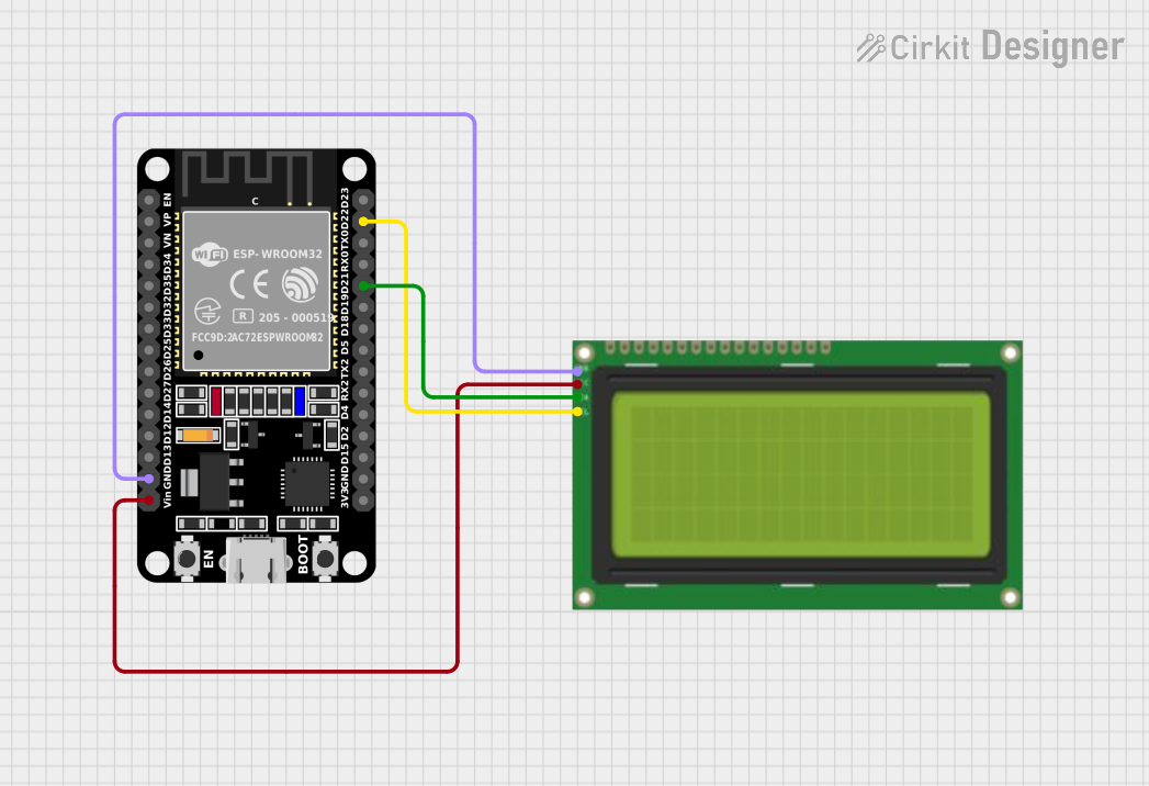
This circuit consists of an ESP32 microcontroller and an LCD 20x4 display with an I2C interface. The ESP32 is a versatile microcontroller with Wi-Fi and Bluetooth capabilities, and it is used here to control and communicate with the LCD display. The LCD display is used to show text or data output from the ESP32. The communication between the ESP32 and the LCD is established via the I2C protocol, which requires only two data lines: SCL (Serial Clock) and SDA (Serial Data).
Component List
ESP32 (30 pin)
- Description: A 30-pin microcontroller with Wi-Fi and Bluetooth capabilities.
- Purpose: Acts as the central processing unit of the circuit, controlling the LCD display and handling data processing and communication.
- Pins: EN, VP, VN, D34, D35, D32, D33, D25, D26, D27, D14, D12, D13, GND, Vin, D23, D22, TX0, RX0, D21, D19, D18, D5, TX2, RX2, D4, D2, D15, 3V3.
Lcd 20x4 i2c
- Description: A 20x4 character LCD display with an I2C interface.
- Purpose: Displays information and data output from the ESP32.
- Pins: GND, 5v, SCA, SCL.
Wiring Details
ESP32 (30 pin)
- GND: Connected to the ground (GND) pin of the LCD display.
- Vin: Connected to the 5v power supply pin of the LCD display.
- D22: Connected to the SCL pin of the LCD display for I2C clock signal.
- D21: Connected to the SCA pin of the LCD display for I2C data signal.
Lcd 20x4 i2c
- GND: Connected to the ground (GND) pin of the ESP32.
- 5v: Connected to the Vin power supply pin of the ESP32.
- SCA: Connected to the D21 pin of the ESP32 for I2C data signal.
- SCL: Connected to the D22 pin of the ESP32 for I2C clock signal.
Documented Code
There is no code provided for the microcontroller in this circuit. Typically, the code would initialize the I2C interface on the ESP32, set up the LCD display, and handle the communication between the ESP32 and the LCD to display text or data. Without the code, the functionality of the circuit cannot be fully described.