
Arduino-Based Health Monitoring System with Temperature and Pulse Sensors
View and Edit Project In Cirkit Designer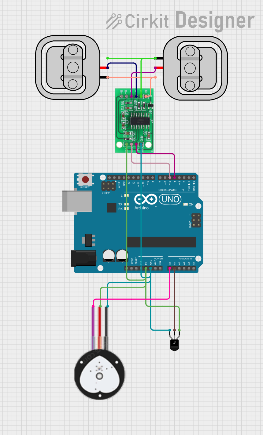
Circuit Documentation
Summary
The circuit in question is designed to interface with multiple sensors, including a temperature sensor (LM35), two load sensors (50kg each), a heart pulse sensor, and an HX711 bridge sensor interface. These sensors are connected to an Arduino UNO microcontroller, which is responsible for processing the sensor data. The temperature sensor and heart pulse sensor provide analog data to the Arduino, while the load sensors interface with the Arduino through the HX711 bridge sensor interface, which communicates digitally. The circuit is powered by a 5V supply from the Arduino, which is distributed to the other components.
Component List
Temperature Sensor (LM35)
- Description: A precision temperature sensor with an analog output proportional to the temperature.
- Pins: +Vs, Vout, GND
Load Sensor - 50kg
- Description: A load sensor capable of measuring up to 50kg of weight.
- Pins: W, R, B
Arduino UNO
- Description: A microcontroller board based on the ATmega328P, with digital and analog I/O pins.
- Pins: UNUSED, IOREF, Reset, 3.3V, 5V, GND, Vin, A0-A5, SCL, SDA, AREF, D0-D13
HX711 - Bridge Sensor Interface
- Description: A precision 24-bit analog-to-digital converter (ADC) designed for weigh scales and industrial control applications to interface directly with a bridge sensor.
- Pins: E+, E-, A-, A+, B-, B+, GND - GROUND, DATA (OUT), SCK - CLOCK (IN), 3.3/3.5V Supply
Heart Pulse Sensor
- Description: A sensor that measures the heart rate of an individual by detecting the pulse through the fingertip.
- Pins: GND, VCC, SIGNAL
Wiring Details
Temperature Sensor (LM35)
- +Vs: Connected to 5V supply
- Vout: Connected to Arduino UNO Analog Pin A1
- GND: Connected to Ground
Load Sensor - 50kg (Two Instances)
- W: Connected to HX711 E+ and E- (for the two sensors respectively)
- R: Connected to HX711 A+ and A- (for the two sensors respectively)
- B: Connected to the other Load Sensor's W pin
Arduino UNO
- 5V: Provides power to Temperature Sensor, Heart Pulse Sensor, and HX711
- GND: Common ground for all components
- A0: Connected to Heart Pulse Sensor SIGNAL
- A1: Connected to Temperature Sensor Vout
- D4: Connected to HX711 DATA (OUT)
- D5: Connected to HX711 SCK - CLOCK (IN)
HX711 - Bridge Sensor Interface
- E+/E-: Connected to Load Sensor W pins
- A+/A-: Connected to Load Sensor R pins
- GND - GROUND: Connected to Ground
- DATA (OUT): Connected to Arduino UNO Digital Pin D4
- SCK - CLOCK (IN): Connected to Arduino UNO Digital Pin D5
- 3.3/3.5V Supply: Connected to 5V supply
Heart Pulse Sensor
- GND: Connected to Ground
- VCC: Connected to 5V supply
- SIGNAL: Connected to Arduino UNO Analog Pin A0
Documented Code
Arduino UNO Code (sketch.ino)
void setup() {
  // put your setup code here, to run once:

}

void loop() {
  // put your main code here, to run repeatedly:

}
Additional Notes
- The provided code is a template and does not include any functionality. The user is expected to write the setup and loop functions to initialize the sensors and process their data.
- The
setup()function is intended to initialize the Arduino pins and any communication protocols. - The
loop()function is where the main logic of the program will run, including reading sensor data and performing actions based on that data. - The code for the Arduino UNO is stored in a file named
sketch.ino. - There is an additional file named
documentation.txt, but it is empty and does not contain any code or information.