Arduino UNO Based Fire Alarm System with Gas and Flame Detection
Circuit Documentation
Summary
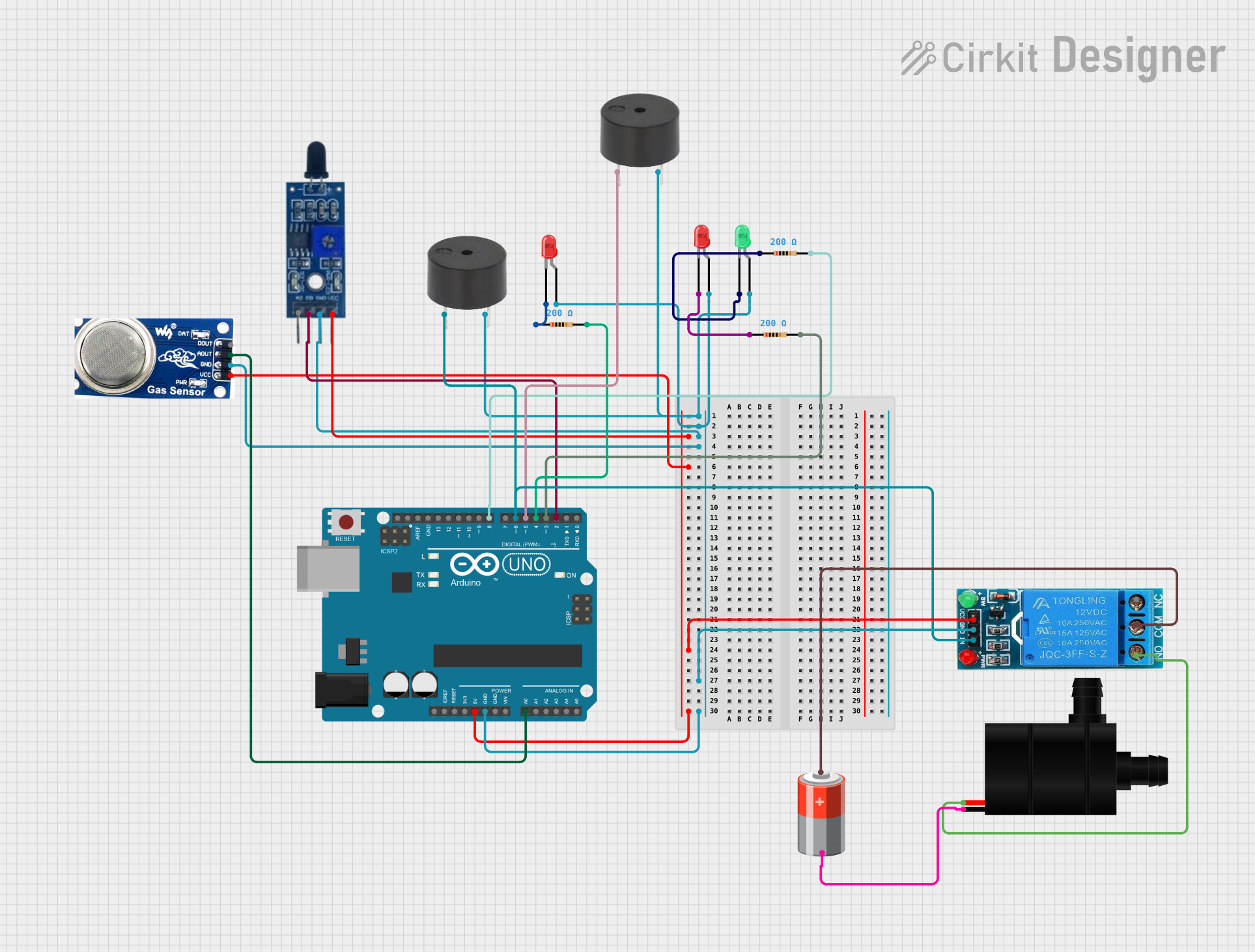
The circuit is designed as a fire alarm system that utilizes an Arduino UNO as the central processing unit. It includes a flame sensor and a smoke sensor for fire detection, two red LEDs, one green LED, and two buzzers for alerting purposes. A 12V single-channel relay is used to control a water pump as part of the fire suppression system. The circuit is powered by a 5V battery. Resistors are used to limit current to the LEDs.
Component List
Arduino UNO
- Microcontroller board based on the ATmega328P.
- It has 14 digital input/output pins, 6 analog inputs, a 16 MHz quartz crystal, a USB connection, a power jack, an ICSP header, and a reset button.
12V Single Channel Relay
- An electrically operated switch that allows you to control a high power circuit with a low power signal.
- It has normally closed (NC), common (COM), and normally open (NO) terminals for switching, as well as an input (IN), ground (GND), and VCC for control.
Flame Sensor
- A device that can detect fire or other wavelengths of light that are from a similar source.
- It has a digital output (D0), an analog output (A0), VCC, and GND.
Smoke Sensor
- A sensor that detects smoke particles in the air.
- It has a digital output (DO), an analog output (AO), VCC, and GND.
LED: Two Pin (red)
- A red light-emitting diode that emits red light when a voltage is applied to its terminals.
- It has an anode and a cathode.
LED: Two Pin (green)
- A green light-emitting diode that emits green light when a voltage is applied to its terminals.
- It has an anode and a cathode.
Buzzer
- An audio signaling device that can be mechanical, electromechanical, or piezoelectric.
- It has a pin for signal input and a GND.
Water Pump
- A device used to move liquids by mechanical action.
- It has VCC and GND.
Resistor (200 Ohms)
- A passive two-terminal electrical component that implements electrical resistance as a circuit element.
- It has two pins and a resistance value of 200 Ohms.
5V Battery
- A power source that provides 5 volts.
- It has a positive (+) and a negative (-) terminal.
Wiring Details
Arduino UNO
- 5V connected to VCC of Flame Sensor, Smoke Sensor, and 12V Single Channel Relay.
- GND connected to GND of all components.
- A0 connected to AO of Smoke Sensor.
- D2 connected to D0 of Flame Sensor.
- D3, D4, D5, D6, D8 connected to respective components through 200 Ohm resistors.
12V Single Channel Relay
- IN connected to D6 of Arduino UNO.
- COM connected to + of 5V Battery.
- NO connected to VCC of Water Pump.
- GND connected to GND of Arduino UNO.
- VCC connected to 5V of Arduino UNO.
Flame Sensor
- VCC connected to 5V of Arduino UNO.
- GND connected to GND of Arduino UNO.
- D0 connected to D2 of Arduino UNO.
Smoke Sensor
- VCC connected to 5V of Arduino UNO.
- GND connected to GND of Arduino UNO.
- AO connected to A0 of Arduino UNO.
LEDs (Red and Green)
- Anodes connected to GND through 200 Ohm resistors.
- Cathodes connected to respective pins on Arduino UNO (D3, D4, D8).
Buzzer
- PIN connected to D5 and D6 of Arduino UNO.
- GND connected to GND of Arduino UNO.
Water Pump
- VCC connected to NO of 12V Single Channel Relay.
- GND connected to - of 5V Battery.
Resistor (200 Ohms)
- One pin connected to anode of LED.
- Other pin connected to respective pins on Arduino UNO (D3, D4, D8).
5V Battery
- connected to COM of 12V Single Channel Relay.
- connected to GND of Water Pump.
Documented Code
/*
www.arduinopoint.com
Fire Alarm System
*/

int redLed1 = 3;
int redLed2 = 4;
int greenLed = 8;
int buzzer1 = 5; //PWM (~) pin
int buzzer2 = 6; //PWM (~) pin
int gasPin = A0;
int flamePin = 2;
// Your threshold value
int gasSensorThres = 400;

void setup() {
  pinMode(redLed1, OUTPUT);
  pinMode(redLed2, OUTPUT);
  pinMode(greenLed, OUTPUT);
  pinMode(buzzer1, OUTPUT);
  pinMode(buzzer2, OUTPUT);
  pinMode(gasPin, INPUT);
  pinMode(flamePin, INPUT);
  Serial.begin(9600);
}

void loop() {
  int gasSensor = analogRead(gasPin);
  int flameSensor = digitalRead(flamePin);

  Serial.print("gasPin Value: ");
  Serial.println(gasSensor);
  Serial.print("flamePin Value: ");
  Serial.println(flameSensor);
  delay(1000);

  if (gasSensor > gasSensorThres  && flameSensor==LOW){
    digitalWrite(redLed1, HIGH);
    tone(buzzer1, 5000); //the buzzer sound frequency at 5000 Hz
    digitalWrite(redLed2, HIGH);
    tone(buzzer2, 5000); //the buzzer sound frequency at 5000 Hz
    digitalWrite(greenLed, LOW);
  }
   else if (gasSensor > gasSensorThres)
  {
    digitalWrite(redLed1, HIGH);
    tone(buzzer1, 5000); //the buzzer sound frequency at 5000 Hz
    digitalWrite(redLed2, LOW);
    noTone(buzzer2);
    digitalWrite(greenLed, LOW);
  }
  else if (flameSensor==LOW){ // HIGH MEANS NO FLAME
    digitalWrite(redLed1, LOW);
    noTone(buzzer1);
    digitalWrite(redLed2, HIGH);
    tone(buzzer2, 5000); //the buzzer sound frequency at 5000 Hz
    digitalWrite(greenLed, LOW);
    }

  else
  {
    digitalWrite(redLed1, LOW);
    digitalWrite(redLed2, LOW);
    noTone(buzzer1);
    noTone(buzzer2);
    digitalWrite(greenLed, HIGH);
  }
}
This code is designed for a fire alarm system. It reads the values from a gas sensor and a flame sensor, and activates different combinations of red and green LEDs and buzzers depending on the sensor readings. If both sensors detect fire conditions, both red LEDs and buzzers are activated. If only the gas sensor detects a fire condition, only one red LED and buzzer are activated. If only the flame sensor detects a fire condition, the other red LED and buzzer are activated. If neither sensor detects a fire condition, the green LED is activated.