
Arduino UNO Motion-Activated Alarm with LED Indicator and Buzzer
View and Edit Project In Cirkit Designer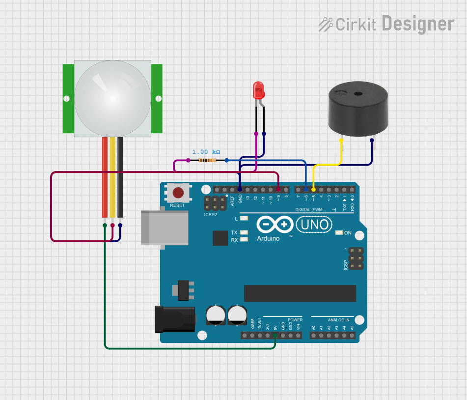
Circuit Documentation
Summary
This circuit is designed to detect motion using a PIR sensor and respond by blinking an LED and sounding a buzzer. The circuit is controlled by an Arduino UNO microcontroller.
Component List
Arduino UNO
- Description: A microcontroller board based on the ATmega328P.
- Pins: UNUSED, IOREF, Reset, 3.3V, 5V, GND, Vin, A0, A1, A2, A3, A4, A5, SCL, SDA, AREF, D13, D12, D11, D10, D9, D8, D7, D6, D5, D4, D3, D2, D1, D0
LED: Two Pin (red)
- Description: A red LED with two pins.
- Pins: cathode, anode
Resistor
- Description: A resistor with a resistance of 1000 Ohms.
- Pins: pin1, pin2
- Properties:
- Resistance: 1000 Ohms
Buzzer
- Description: A simple buzzer.
- Pins: PIN, GND
PIR Sensor
- Description: A Passive Infrared (PIR) sensor for motion detection.
- Pins: VDD, SIG, GND
Wiring Details
Arduino UNO
- 5V: Connected to VDD of the PIR sensor.
- GND: Connected to GND of the PIR sensor, GND of the buzzer, and anode of the LED.
- D9: Connected to SIG of the PIR sensor.
- D6: Connected to pin2 of the resistor.
- D5: Connected to PIN of the buzzer.
LED: Two Pin (red)
- cathode: Connected to pin1 of the resistor.
- anode: Connected to GND of the Arduino UNO.
Resistor
- pin1: Connected to cathode of the LED.
- pin2: Connected to D6 of the Arduino UNO.
Buzzer
- PIN: Connected to D5 of the Arduino UNO.
- GND: Connected to GND of the Arduino UNO.
PIR Sensor
- VDD: Connected to 5V of the Arduino UNO.
- SIG: Connected to D9 of the Arduino UNO.
- GND: Connected to GND of the Arduino UNO.
Code Documentation
Code Overview
The code initializes the pins for the LED, buzzer, and PIR sensor. When motion is detected by the PIR sensor, the LED blinks 20 times, and the buzzer sounds for 3 seconds.
Code
int led = 6;
int buz = 5;
int sig = 9;

void setup() {
  pinMode(led, OUTPUT);
  pinMode(buz, OUTPUT);
  pinMode(sig, INPUT);
}

void loop() {
  int motion = digitalRead(sig);
  if (motion == HIGH) {
    for (int i = 0; i < 20; i++) {
      digitalWrite(led, HIGH);
      delay(250);
      digitalWrite(led, LOW);
      delay(250);
    }
    digitalWrite(buz, HIGH);
    delay(3000);
    digitalWrite(buz, LOW);
  }
}
Code Explanation
- Variables:
ledis assigned to pin 6.buzis assigned to pin 5.sigis assigned to pin 9.
- Setup Function:
pinMode(led, OUTPUT)sets the LED pin as an output.pinMode(buz, OUTPUT)sets the buzzer pin as an output.pinMode(sig, INPUT)sets the PIR sensor pin as an input.
- Loop Function:
digitalRead(sig)reads the state of the PIR sensor.- If motion is detected (
motion == HIGH), the LED blinks 20 times with a 250ms delay between each blink. - After blinking, the buzzer sounds for 3 seconds (
3000ms).
This documentation provides a comprehensive overview of the circuit, including the components used, their wiring, and the code that controls the circuit.