Cirkit Designer
Your all-in-one circuit design IDE
Home /
Project Documentation
Battery-Powered Weather Station with Arduino Nano and SD Card Logging
Circuit Documentation
Summary
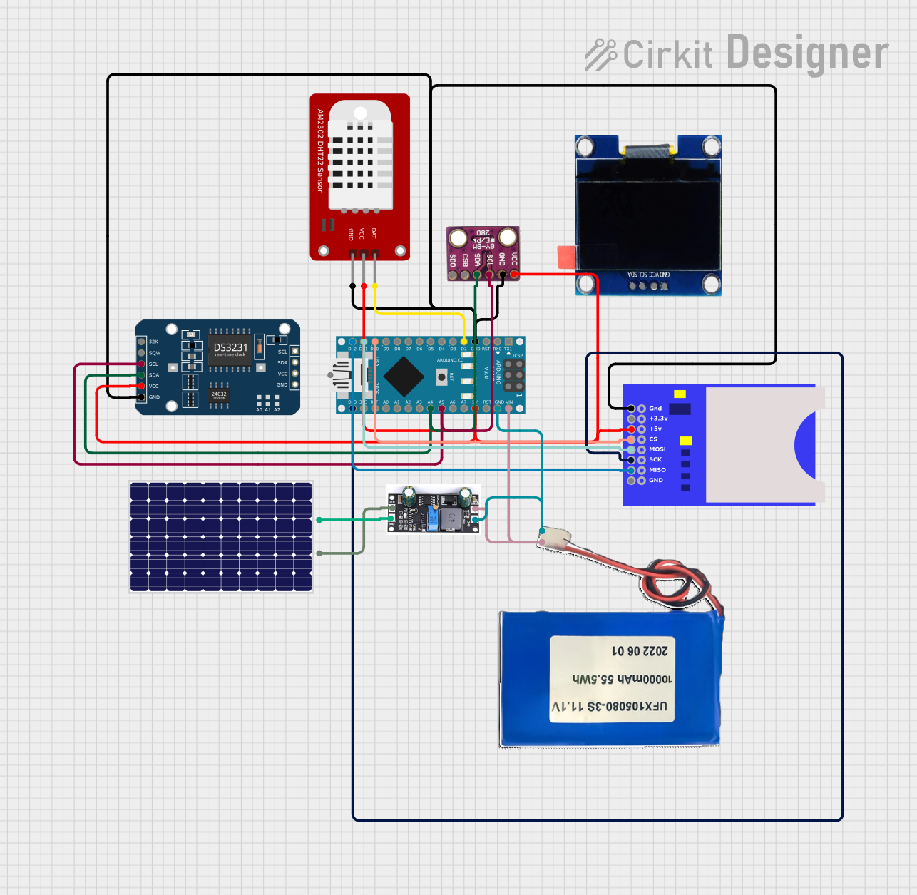
This circuit is designed to monitor environmental conditions such as temperature, humidity, and atmospheric pressure. It utilizes various sensors and modules, including a DHT22 for temperature and humidity readings, a BMP280 for pressure measurements, and an SD card module for data logging. The Arduino Nano serves as the central microcontroller, coordinating the data collection and storage processes. The circuit is powered by a lithium-ion battery, which is charged via a solar panel and managed by a charge controller.
Component List
1. Arduino Nano
- Description: A compact microcontroller board based on the ATmega328P.
- Purpose: Acts as the main controller for the circuit, processing sensor data and managing communication with the SD card.
2. BMP280
- Description: A digital barometer and temperature sensor.
- Purpose: Measures atmospheric pressure and temperature for environmental monitoring.
3. Solar Panel
- Description: A photovoltaic panel that converts sunlight into electrical energy.
- Purpose: Provides power to the circuit through the charge controller.
4. Charge Controller
- Description: A device that regulates the voltage and current coming from the solar panel to the battery.
- Purpose: Ensures safe charging of the lithium-ion battery.
5. SD Card Module
- Description: A module that allows for the reading and writing of data to an SD card.
- Purpose: Stores logged environmental data for later retrieval and analysis.
6. Lithium-ion Battery 10000mAh
- Description: A rechargeable battery that provides power to the circuit.
- Purpose: Supplies energy to the components when solar power is insufficient.
7. DHT22
- Description: A digital temperature and humidity sensor.
- Purpose: Measures the ambient temperature and humidity levels.
8. DS3231 RTC
- Description: A real-time clock module.
- Purpose: Keeps track of the current date and time for timestamping logged data.
Wiring Details
Arduino Nano
- GND: Connected to GND of DHT22, BMP280, SD card module, and charge controller.
- D2: Connected to DAT pin of DHT22.
- D10: Connected to CS pin of SD card module.
- D11/MOSI: Connected to MOSI pin of SD card module.
- D12/MISO: Connected to MISO pin of SD card module.
- VIN: Connected to 11.1V pin of lithium-ion battery and BAT pin of charge controller.
- 5V: Connected to VCC of DS3231, DHT22, BMP280, and +5V of SD card module.
- A5: Connected to SCL pin of DS3231 and BMP280.
- A4: Connected to SDA pin of DS3231 and BMP280.
- D13/SCK: Connected to SCK pin of SD card module.
BMP280
- GND: Connected to GND of Arduino Nano.
- VCC: Connected to 5V of Arduino Nano.
- SCL: Connected to A5 of Arduino Nano.
- SDA: Connected to A4 of Arduino Nano.
DHT22
- GND: Connected to GND of Arduino Nano.
- VCC: Connected to 5V of Arduino Nano.
- DAT: Connected to D2 of Arduino Nano.
DS3231 RTC
- GND: Connected to GND of Arduino Nano.
- VCC: Connected to 5V of Arduino Nano.
- SCL: Connected to A5 of Arduino Nano.
- SDA: Connected to A4 of Arduino Nano.
SD Card Module
- GND: Connected to GND of Arduino Nano.
- +5V: Connected to 5V of Arduino Nano.
- CS: Connected to D10 of Arduino Nano.
- MOSI: Connected to D11 of Arduino Nano.
- MISO: Connected to D12 of Arduino Nano.
- SCK: Connected to D13 of Arduino Nano.
Lithium-ion Battery 10000mAh
- GND: Connected to GND of Arduino Nano and charge controller.
- 11.1V: Connected to VIN of Arduino Nano and BAT of charge controller.
Charge Controller
- GND: Connected to GND of lithium-ion battery and Arduino Nano.
- Vin: Connected to + of solar panel.
- BAT: Connected to VIN of Arduino Nano.
Solar Panel
- +: Connected to Vin of charge controller.
- -: Connected to GND of charge controller.
Documented Code
#include <Wire.h>
#include <Adafruit_Sensor.h>
#include <DHT.h>
#include <Adafruit_BMP280.h>  // If using BMP280, use this library
#include <SD.h>
#include <RTClib.h>

#define DHTPIN 2          // DHT22 data pin
#define DHTTYPE DHT22
#define SD_CS_PIN 10      // SD Card CS pin

DHT dht(DHTPIN, DHTTYPE);
Adafruit_BMP280 bmp;  // Change to BMP280 if using this sensor
RTC_DS3231 rtc;
File dataFile;

void setup() {
  Serial.begin(9600);
  dht.begin();

  // Initialize BMP280 Sensor
  if (!bmp.begin()) {
    Serial.println("BMP280 sensor not detected!");
    while (1);  // Stop execution if sensor is not detected
  }

  // Initialize RTC Module
  if (!rtc.begin()) {
    Serial.println("RTC module not detected!");
    while (1);  // Stop execution if RTC is not detected
  }

  // Initialize SD Card
  if (!SD.begin(SD_CS_PIN)) {
    Serial.println("SD Card initialization failed!");
    return;  // Stop further execution if SD card fails
  }

  // Write header to the SD file
  dataFile = SD.open("weather_log.txt", FILE_WRITE);
  if (dataFile) {
    dataFile.println("Date Time, Temperature (C), Humidity (%), Pressure (hPa)");
    dataFile.close();
  } else {
    Serial.println("Failed to open weather log file.");
  }
}

void loop() {
  float humidity = dht.readHumidity();
  float temperature = dht.readTemperature();
  float pressure = bmp.readPressure() / 100.0F;  // Convert pressure to hPa

  // Check if any reading fails, skip logging that iteration
  if (isnan(temperature) || isnan(humidity)) {
    Serial.println("Failed to read from DHT sensor!");
    return;
  }

  // Get current time from RTC
  DateTime now = rtc.now();
  String timestamp = String(now.year()) + "-" + String(now.month()) + "-" + String(now.day()) + " " +
                     String(now.hour()) + ":" + String(now.minute()) + ":" + String(now.second());

  // Print to Serial Monitor
  Serial.print(timestamp);
  Serial.print(", ");
  Serial.print(temperature);
  Serial.print(", ");
  Serial.print(humidity);
  Serial.print(", ");
  Serial.println(pressure);

  // Write to SD card
  dataFile = SD.open("weather_log.txt", FILE_WRITE);
  if (dataFile) {
    dataFile.print(timestamp);
    dataFile.print(", ");
    dataFile.print(temperature);
    dataFile.print(", ");
    dataFile.print(humidity);
    dataFile.print(", ");
    dataFile.println(pressure);
    dataFile.close();
  } else {
    Serial.println("Failed to open weather log file.");
  }

  delay(60000);  // Log data every minute
}
This documentation provides a comprehensive overview of the circuit, detailing each component, its purpose, wiring connections, and the code used for operation.