
Arduino UNO-Based Smart Home Monitoring System with Wi-Fi Connectivity
View and Edit Project In Cirkit Designer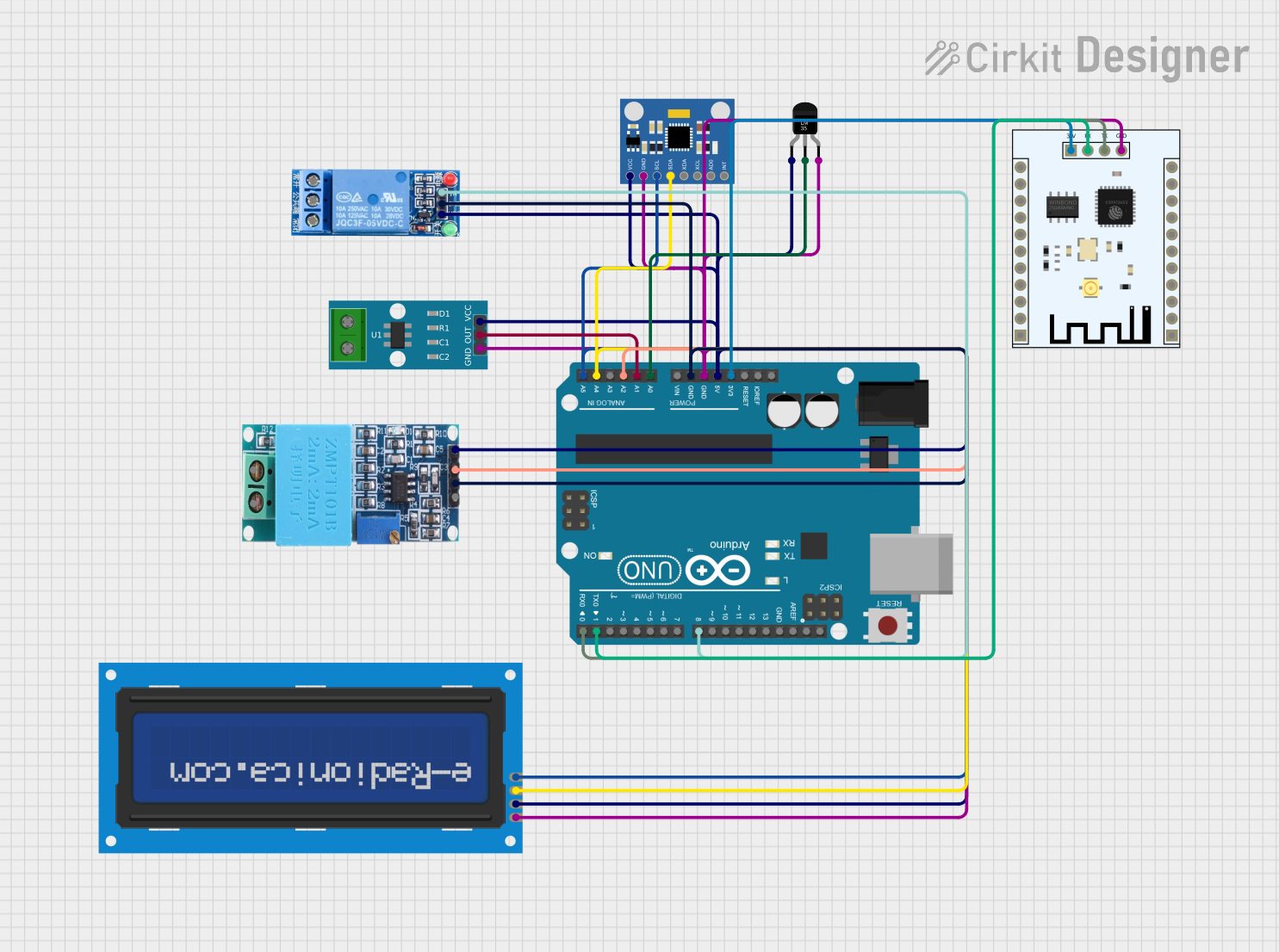
Circuit Documentation
Summary
This circuit integrates an Arduino UNO microcontroller with various sensors and modules, including an MPU6050 Accelerometer + Gyroscope, a Temperature Sensor (LM35), an ACS712 Current Sensor, a ZMPT101B Voltage Sensor, a 1 Channel Relay, an LCD screen, and an ESP8266 WiFi Module. The Arduino UNO serves as the central controller, interfacing with the sensors and modules to collect data and control outputs.
Component List
Arduino UNO
- Description: Microcontroller board based on the ATmega328P.
- Pins: UNUSED, IOREF, Reset, 3.3V, 5V, GND, Vin, A0, A1, A2, A3, A4, A5, SCL, SDA, AREF, D13, D12, D11, D10, D9, D8, D7, D6, D5, D4, D3, D2, D1, D0
MPU6050 Accelerometer + Gyroscope (Wokwi Compatible)
- Description: 6-axis motion tracking device.
- Pins: INT, AD0, XCL, XDA, SDA, SCL, GND, VCC
Temperature Sensor (LM35)
- Description: Precision centigrade temperature sensor.
- Pins: +Vs, Vout, GND
ACS712 Current Sensor 5A 20A 30A
- Description: Current sensor module.
- Pins: 1, 2, GND, OUT, VCC
ZMPT101B
- Description: Voltage sensor module.
- Pins: OUT, GND, VCC, NEUTRO, FASE
1 Channel Relay 5V
- Description: Relay module for switching high voltage devices.
- Pins: VCC, GND, IN, NC, COM, NO
LCD screen 16x2 I2C
- Description: 16x2 character LCD display with I2C interface.
- Pins: SCL, SDA, VCC, GND
ESP8266 ESP-201 WiFi Module
- Description: WiFi module for wireless communication.
- Pins: 3.3V, IO4, D3, D1, D0, CMD, CLK, D2, IO2, IO0, GND, IO5, T_OUT, RST, CHIP_EN, XPD, IO14, IO12, IO13, IO15, RX, TX
Wiring Details
Arduino UNO
- 3.3V: Connected to ESP8266 ESP-201 WiFi Module (3.3V)
- 5V: Connected to 1 Channel Relay 5V (VCC), LCD screen 16x2 I2C (VCC), ACS712 Current Sensor 5A 20A 30A (VCC), ZMPT101B (VCC), MPU6050 Accelerometer + Gyroscope (VCC), Temperature Sensor (LM35) (+Vs)
- GND: Connected to LCD screen 16x2 I2C (GND), ACS712 Current Sensor 5A 20A 30A (GND), MPU6050 Accelerometer + Gyroscope (GND), ESP8266 ESP-201 WiFi Module (GND), Temperature Sensor (LM35) (GND), 1 Channel Relay 5V (GND), ZMPT101B (GND)
- A0: Connected to Temperature Sensor (LM35) (Vout)
- A1: Connected to ACS712 Current Sensor 5A 20A 30A (OUT)
- A2: Connected to ZMPT101B (OUT)
- A4: Connected to LCD screen 16x2 I2C (SDA), MPU6050 Accelerometer + Gyroscope (SDA)
- A5: Connected to LCD screen 16x2 I2C (SCL), MPU6050 Accelerometer + Gyroscope (SCL)
- D8: Connected to 1 Channel Relay 5V (IN)
- D1: Connected to ESP8266 ESP-201 WiFi Module (RX)
- D0: Connected to ESP8266 ESP-201 WiFi Module (TX)
MPU6050 Accelerometer + Gyroscope (Wokwi Compatible)
- VCC: Connected to Arduino UNO (5V)
- GND: Connected to Arduino UNO (GND)
- SDA: Connected to Arduino UNO (A4)
- SCL: Connected to Arduino UNO (A5)
Temperature Sensor (LM35)
- +Vs: Connected to Arduino UNO (5V)
- Vout: Connected to Arduino UNO (A0)
- GND: Connected to Arduino UNO (GND)
ACS712 Current Sensor 5A 20A 30A
- VCC: Connected to Arduino UNO (5V)
- GND: Connected to Arduino UNO (GND)
- OUT: Connected to Arduino UNO (A1)
ZMPT101B
- VCC: Connected to Arduino UNO (5V)
- GND: Connected to Arduino UNO (GND)
- OUT: Connected to Arduino UNO (A2)
1 Channel Relay 5V
- VCC: Connected to Arduino UNO (5V)
- GND: Connected to Arduino UNO (GND)
- IN: Connected to Arduino UNO (D8)
LCD screen 16x2 I2C
- VCC: Connected to Arduino UNO (5V)
- GND: Connected to Arduino UNO (GND)
- SDA: Connected to Arduino UNO (A4)
- SCL: Connected to Arduino UNO (A5)
ESP8266 ESP-201 WiFi Module
- 3.3V: Connected to Arduino UNO (3.3V)
- GND: Connected to Arduino UNO (GND)
- RX: Connected to Arduino UNO (D1)
- TX: Connected to Arduino UNO (D0)
Documented Code
Arduino UNO Code (sketch.ino)
void setup() {
  // put your setup code here, to run once:

}

void loop() {
  // put your main code here, to run repeatedly:

}
Additional Documentation (documentation.txt)