ESP32-Controlled Dual Motor Driver with Optical Encoder Feedback

Circuit Documentation
Summary
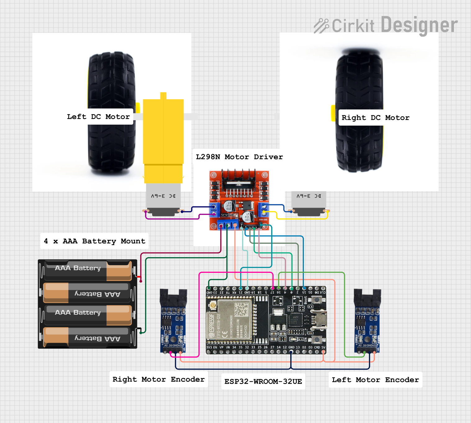
This circuit is designed to control a dual motor system with PWM control, using an L298N 2A Dual Motor Driver Module. It is powered by a 4 x AAA battery mount and includes two optical encoder sensor modules for feedback. The ESP32-WROOM-32UE microcontroller is used to interface with the motor driver and the encoders, providing control signals and processing the encoder outputs. The motors are hobbyist yellow gear motors, and their speed and direction are controlled by the L298N module, which receives its commands from the ESP32.
Component List
L298N 2A Dual Motor Driver Module with PWM Control
- Description: A module capable of driving two motors with up to 2A per channel.
- Pins: OUT1, OUT2, 12V, GND, 5V, OUT4, OUT3, ENA, IN1, IN2, IN3, ENB, IN4
4 x AAA Battery Mount
- Description: A battery holder for four AAA batteries, providing power to the circuit.
- Pins: -, +
Optical Encoder Sensor Module (x2)
- Description: Sensor modules that provide feedback on motor rotation, typically used for precise control of motor speed and position.
- Pins: A0, D0, GND, VCC
Motor Amarillo Motorreductor Hobby (x2)
- Description: Yellow gear motors commonly used in hobbyist projects for propulsion.
- Pins: vcc, GND
ESP32-WROOM-32UE
- Description: A powerful microcontroller with Wi-Fi and Bluetooth capabilities, used for controlling the motor driver and processing encoder signals.
- Pins: 3v3, EN, VP, VN, 34, 35, 32, 33, 25, 26, 27, 14, 12, GND, 13, D2, D3, 5V, 23, 22, TX, RX, 21, 19, 18, 5, 17, 16, 4, 0, 2, 15, D1, D0, CKL
Wheels (x2)
- Description: Wheels attached to the motors to enable movement.
Comments (x6)
- Description: Placeholder components that may represent annotations or notes in the circuit design.
Wiring Details
L298N 2A Dual Motor Driver Module with PWM Control
- 5V connected to ESP32-WROOM-32UE (5V) and Optical Encoder Sensor Modules (VCC)
- GND connected to 4 x AAA Battery Mount (-), ESP32-WROOM-32UE (GND), and Optical Encoder Sensor Modules (GND)
- 12V connected to 4 x AAA Battery Mount (+)
- ENA connected to ESP32-WROOM-32UE (GND)
- ENB connected to ESP32-WROOM-32UE (21)
- IN1 connected to ESP32-WROOM-32UE (15)
- IN2 connected to ESP32-WROOM-32UE (2)
- IN3 connected to ESP32-WROOM-32UE (0)
- IN4 connected to ESP32-WROOM-32UE (4)
- OUT1 connected to Motor Amarillo Motorreductor Hobby (GND)
- OUT2 connected to Motor Amarillo Motorreductor Hobby (vcc)
- OUT3 connected to Motor Amarillo Motorreductor Hobby (GND)
- OUT4 connected to Motor Amarillo Motorreductor Hobby (vcc)
Optical Encoder Sensor Module
- GND connected to ESP32-WROOM-32UE (GND)
- VCC connected to L298N Module (5V) and ESP32-WROOM-32UE (5V)
- D0 connected to ESP32-WROOM-32UE (17 for one module, 16 for the other)
Motor Amarillo Motorreductor Hobby
- vcc connected to L298N Module (OUT2 for one motor, OUT4 for the other)
- GND connected to L298N Module (OUT1 for one motor, OUT3 for the other)
ESP32-WROOM-32UE
- GND connected to L298N Module (GND), Optical Encoder Sensor Modules (GND), and 4 x AAA Battery Mount (-)
- 5V connected to L298N Module (5V) and Optical Encoder Sensor Modules (VCC)
- 21 connected to L298N Module (ENB)
- 17 connected to Optical Encoder Sensor Module (D0)
- 16 connected to Optical Encoder Sensor Module (D0)
- 15 connected to L298N Module (IN1)
- 2 connected to L298N Module (IN2)
- 0 connected to L298N Module (IN3)
- 4 connected to L298N Module (IN4)
Documented Code
No code has been provided for the ESP32-WROOM-32UE microcontroller. The code would typically include initialization of the GPIO pins, setup of PWM channels for motor control, and routines to read the encoder outputs and adjust motor speeds accordingly.