
ESP8266 NodeMCU and Arduino UNO Based Smart Irrigation System
View and Edit Project In Cirkit Designer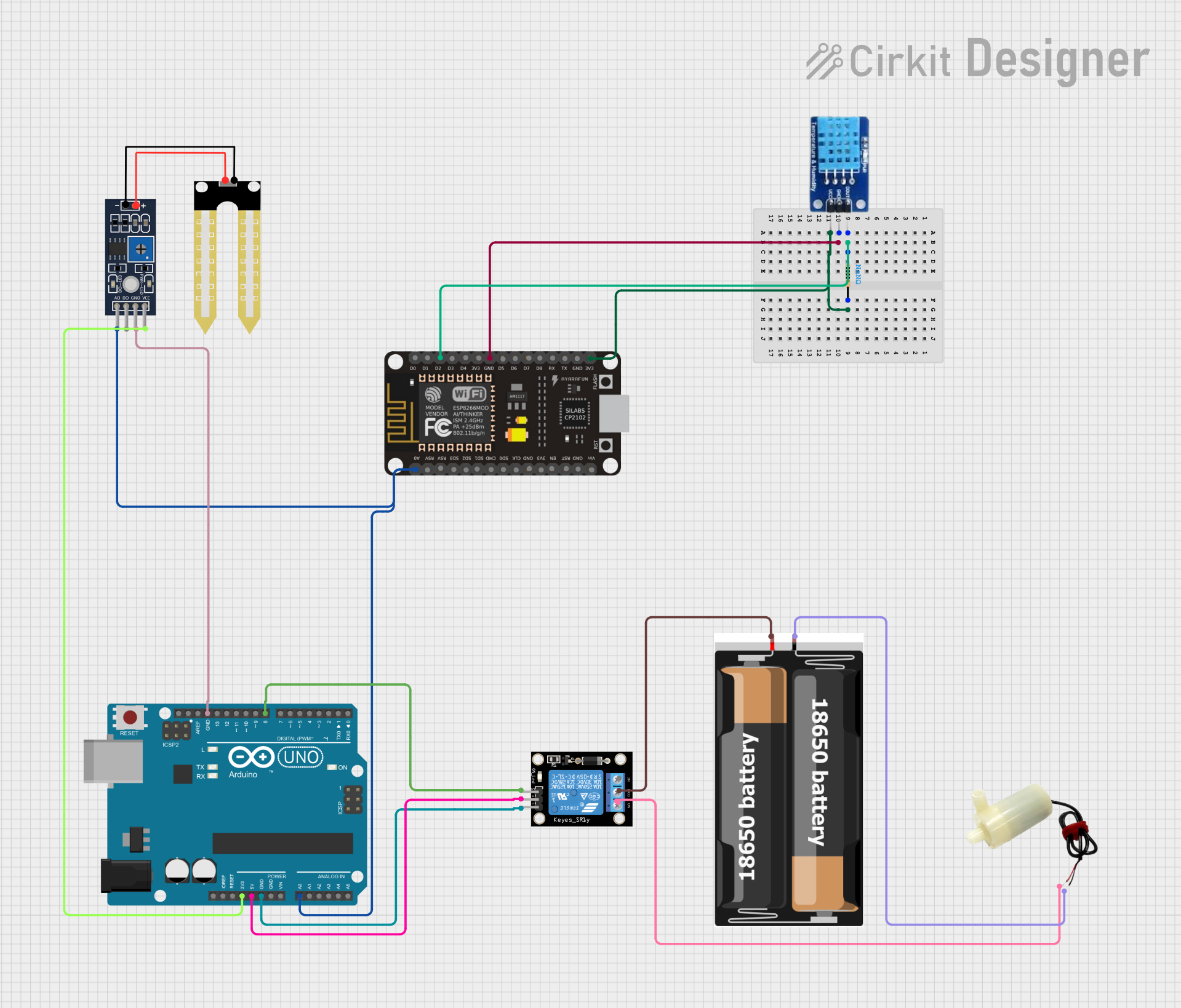
Circuit Documentation
Summary
The circuit in question appears to be a control system utilizing an ESP8266 NodeMCU and an Arduino UNO as microcontrollers. The system includes a DHT11 temperature and humidity sensor, a YL-69 soil moisture sensor, a 1-channel relay module to control a 5V mini water pump, and a resistor whose value is not specified. The power supply for the circuit is provided by two 18650 batteries. The ESP8266 NodeMCU is interfaced with the DHT11 sensor, while the Arduino UNO is connected to both the YL-69 sensor and the relay module which controls the water pump.
Component List
ESP8266 NodeMCU
- Microcontroller with WiFi capability.
- Pins: D0-D8, RX, TX, A0, RSV, SD3, SD2, SD1, CMD, SD0, CLK, EN, RST, VIN, 3V3, GND.
DHT11
- Temperature and humidity sensor.
- Pins: DATA, GND, VCC.
Resistor
- Passive component used to limit current or divide voltages.
- Value: Not specified (NaN Ohms).
- Pins: pin1, pin2.
Relay Module 1 Channel
- Electromechanical switch used to control high power devices.
- Pins: S, 5V, GND, NC, COM, NO.
5V Mini Water Pump
- Pump used for moving water.
- Pins: positive pin, negative pin.
Humidity YL-69
- Soil moisture sensor.
- Pins: A0, D0, GND, VCC.
Arduino UNO
- Microcontroller board based on the ATmega328P.
- Pins: UNUSED, IOREF, Reset, 3.3V, 5V, GND, Vin, A0-A5, SCL, SDA, AREF, D0-D13.
2x 18650 Batteries
- Power source for the circuit.
- Pins: vcc, gnd.
Wiring Details
ESP8266 NodeMCU
- D2 connected to DHT11 DATA through a Resistor.
- 3V3 connected to one end of the Resistor and DHT11 VCC.
- GND connected to DHT11 GND.
- A0 connected to Arduino UNO A0 and YL-69 A0.
DHT11
- DATA connected to ESP8266 NodeMCU D2 through a Resistor.
- VCC connected to ESP8266 NodeMCU 3V3.
- GND connected to ESP8266 NodeMCU GND.
Resistor
- pin1 connected to DHT11 DATA.
- pin2 connected to ESP8266 NodeMCU 3V3.
Relay Module 1 Channel
- S connected to Arduino UNO D8.
- 5V connected to Arduino UNO 5V.
- GND connected to Arduino UNO GND.
- COM connected to 2x 18650 vcc.
- NO connected to 5V Mini Water Pump positive pin.
5V Mini Water Pump
- positive pin connected to Relay Module NO.
- negative pin connected to 2x 18650 gnd.
Humidity YL-69
- A0 connected to Arduino UNO A0.
- GND connected to Arduino UNO GND.
- VCC connected to Arduino UNO 3.3V.
Arduino UNO
- A0 connected to ESP8266 NodeMCU A0 and YL-69 A0.
- D8 connected to Relay Module S.
- 5V connected to Relay Module 5V.
- GND connected to Relay Module GND, YL-69 GND, and 5V Mini Water Pump negative pin.
- 3.3V connected to YL-69 VCC.
2x 18650 Batteries
- vcc connected to Relay Module COM.
- gnd connected to 5V Mini Water Pump negative pin.
Documented Code
Arduino UNO Code (sketch.ino)
void setup() {
  // put your setup code here, to run once:

}

void loop() {
  // put your main code here, to run repeatedly:

}
Note: The provided code for the Arduino UNO is a template with empty setup and loop functions. The actual functionality needs to be implemented based on the requirements of the circuit.
Additional Files
- A text file named "documentation.txt" is mentioned, but it contains no code or text.