Arduino UNO Controlled RFID and IR Sensor Security System with Servo Lock and Alert Indicators
Circuit Documentation
Summary
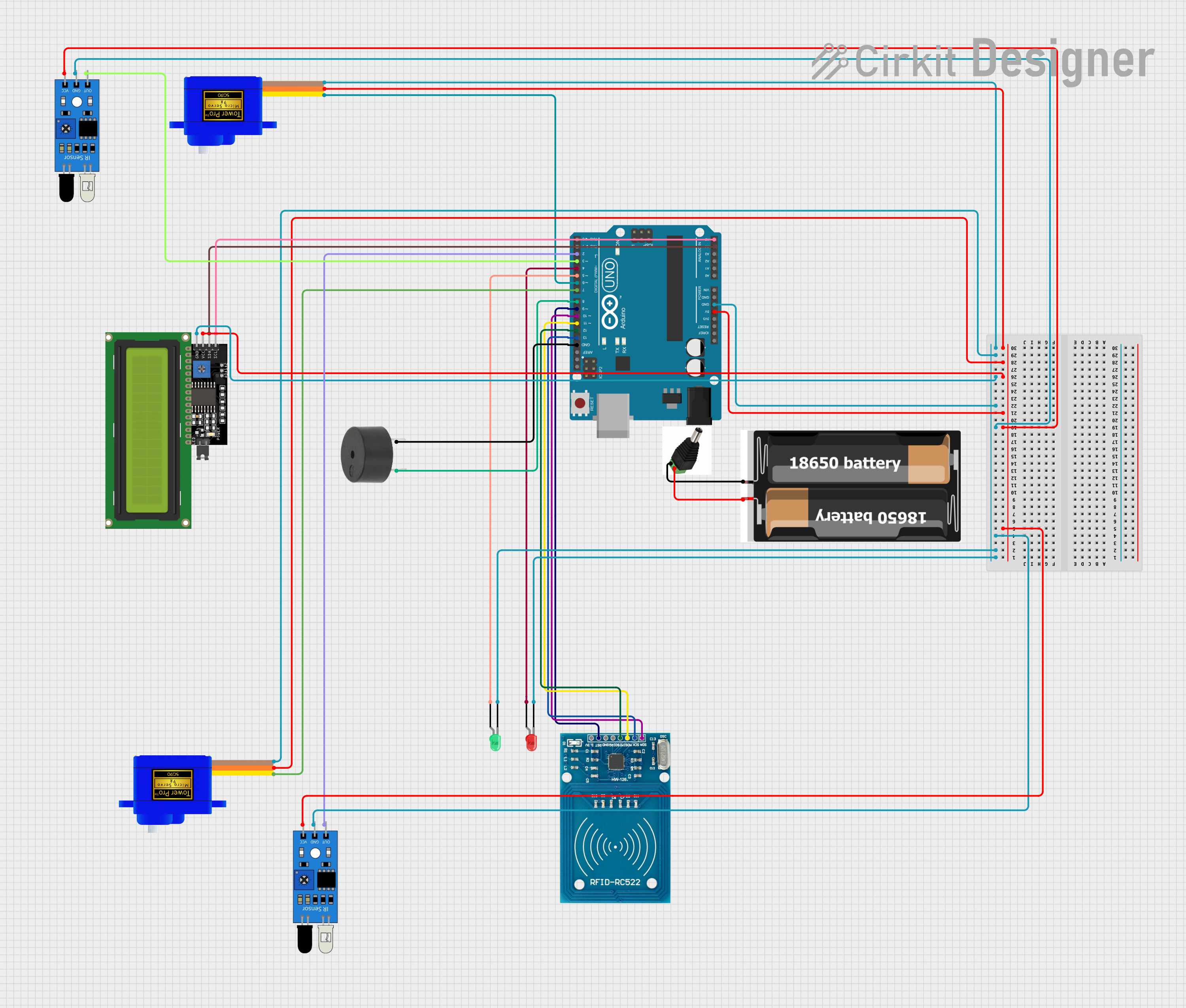
This circuit integrates various components including servomotors, a buzzer, an RFID module, LEDs, IR sensors, a power source, an Arduino UNO microcontroller, and an LCD display. The circuit is designed to perform tasks that likely involve motion control with the servomotors, identification or security features with the RFID module, visual feedback with LEDs, distance or presence detection with IR sensors, user interaction with the buzzer, and data display with the LCD. The Arduino UNO serves as the central processing unit, controlling the various peripherals through its GPIO pins.
Component List
- Servomotor SG90: A small and lightweight servo used for motion control.
- Buzzer: An electronic buzzer for audible feedback.
- RFID-RC522: An RFID reader/writer module for wireless communication and identification.
- LED (Red and Green): Light Emitting Diodes for visual indication.
- IR Sensor: Infrared sensors for object detection or distance measurement.
- 2x 18650 Battery: A power source consisting of two 18650 lithium-ion batteries.
- Arduino UNO: A microcontroller board based on the ATmega328P, used for controlling the circuit.
- LCD Display 16x4 I2C: A 16x4 character LCD display with an I2C interface for displaying data.
- DC Power Jack: A connector for supplying power to the circuit from an external source.
Wiring Details
Servomotor SG90
- SIG: Connected to Arduino UNO Digital Pin D7 (for one servo) and D6 (for the other servo).
- VCC: Connected to the 5V power rail from the Arduino UNO.
- GND: Connected to the ground rail.
Buzzer
- PIN: Connected to Arduino UNO Digital Pin D8.
- GND: Connected to the ground rail.
RFID-RC522
- SCK: Connected to Arduino UNO Digital Pin D13.
- MISO: Connected to Arduino UNO Digital Pin D12.
- MOSI: Connected to Arduino UNO Digital Pin D11.
- SDA: Connected to Arduino UNO Digital Pin D10.
- RST: Connected to Arduino UNO Digital Pin D9.
- VCC (3.3V): Should be connected to a 3.3V power source (not specified in the net list).
- GND: Should be connected to the ground rail (not specified in the net list).
- IRQ: Not connected (unused in this configuration).
LED: Two Pin (Red and Green)
- Cathode (Red and Green): Connected to the ground rail.
- Anode (Red): Connected to Arduino UNO Digital Pin D4.
- Anode (Green): Connected to Arduino UNO Digital Pin D5.
IR Sensor
- Out: Connected to Arduino UNO Digital Pin D2 (for one sensor) and D3 (for the other sensor).
- GND: Connected to the ground rail.
- VCC: Connected to the 5V power rail from the Arduino UNO.
2x 18650 Battery
- VCC: Connected to the DC Power Jack +ve.
- GND: Connected to the DC Power Jack -ve.
Arduino UNO
- 5V: Provides power to the 5V power rail.
- GND: Connected to the ground rail.
- Digital Pins (D2-D13): Connected to various components as specified above.
- Analog Pins (A4, A5): Connected to the I2C pins of the LCD Display (A4 to SDA, A5 to SCL).
LCD Display 16x4 I2C
- SDA: Connected to Arduino UNO Analog Pin A4.
- SCL: Connected to Arduino UNO Analog Pin A5.
- VCC: Connected to the 5V power rail from the Arduino UNO.
- GND: Connected to the ground rail.
DC Power Jack
- +ve: Connected to the +ve terminal of the 2x 18650 Battery.
- -ve: Connected to the -ve terminal of the 2x 18650 Battery.
Documented Code
Arduino UNO Code (sketch.ino)
void setup() {
  // put your setup code here, to run once:

}

void loop() {
  // put your main code here, to run repeatedly:

}
Note: The provided code is a template and does not include any functionality. It needs to be populated with the logic to control the components based on the requirements of the circuit's application.
Additional Documentation (documentation.txt)
No additional documentation code was provided.