Cirkit Designer
Your all-in-one circuit design IDE
Home /
Project Documentation
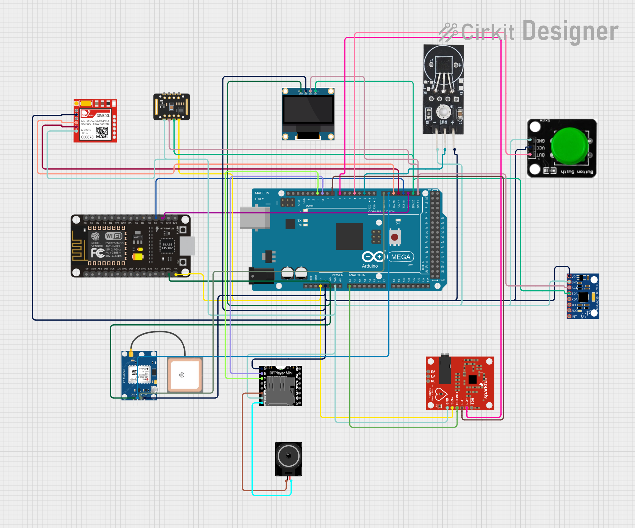
Arduino Mega 2560 and ESP8266 Based Multi-Sensor Health Monitoring System with GPS and GSM

Circuit Documentation
Summary
This circuit is designed to monitor various health parameters and environmental conditions. It includes an Arduino Mega 2560 as the main microcontroller, interfaced with a variety of sensors and modules such as the ESP8266 NodeMCU for WiFi connectivity, a GPS module for location tracking, a GSM module for communication, and various sensors for measuring temperature, heart rate, and blood oxygen levels. The circuit also features an OLED display for data visualization, a DFPlayer Mini for audio output, and a panic/emergency button.
Component List
Microcontrollers
- ESP8266 NodeMCU: A WiFi module that allows the circuit to connect to the internet.
- Arduino Mega 2560: The primary microcontroller used for processing and controlling the various components in the circuit.
Sensors and Modules
- 0.96" OLED: A small display for showing information and readings from the sensors.
- Sim800l: A GSM/GPRS module for cellular communication.
- MAX30102: A pulse oximetry and heart-rate monitor sensor.
- DS18B20 Temperature Sensor: A digital temperature sensor for measuring environmental temperature.
- Green Button: A push button that can be used as an emergency alert trigger.
- MPU-6050: A motion tracking device with a 3-axis gyroscope and a 3-axis accelerometer.
- AD8232 Heart Rate Monitor: A single-lead heart rate monitor for measuring electrocardiography (ECG) signals.
- DFPlayer MINI: A small sound module capable of playing back stored sound files.
- Loudspeaker: An audio output device for the DFPlayer Mini.
- GPS NEO 6M: A GPS module for location tracking.
Wiring Details
ESP8266 NodeMCU
- RX: Connected to Arduino Mega 2560 TX1 (D18)
- TX: Connected to Arduino Mega 2560 RX1 (D19)
- GND: Common ground with Arduino Mega 2560 and other components
- VIN: Powered by the 3.3V output from Arduino Mega 2560
Arduino Mega 2560
- D18/TX1: Connected to ESP8266 NodeMCU RX
- D19/RX1: Connected to ESP8266 NodeMCU TX
- GND: Common ground with all components
- 3V3: Powers the ESP8266 NodeMCU, MAX30102, and AD8232 HeartRate Monitor
- 5V: Powers the Green Button, DFPlayer MINI, GPS NEO 6M, Sim800l, DS18B20 Temperature Sensor, 0.96" OLED, and MPU-6050
- A0: Connected to AD8232 HeartRate Monitor OUTPUT
- D21/SCL: Connected to MAX30102 SCL, 0.96" OLED SCK, and MPU-6050 SCL
- D20/SDA: Connected to MAX30102 SDA, 0.96" OLED SDA, and MPU-6050 SDA
- D17 PWM/RX2: Connected to Sim800l TXD
- D16 PWM/TX2: Connected to Sim800l RXD
- D15/RX3: Connected to GPS NEO 6M TX
- D14/TX3: Connected to GPS NEO 6M RX
- D2 PWM: Connected to DS18B20 Temperature Sensor OUT
- D4 PWM: Connected to Green Button OUT
- D7 PWM: Connected to AD8232 HeartRate Monitor LO+
- D8 PWM: Connected to AD8232 HeartRate Monitor LO-
- D10 PWM: Connected to DFPlayer MINI RX
- D11 PWM: Connected to DFPlayer MINI TX
0.96" OLED
- GND: Common ground
- VDD: Powered by the 5V output from Arduino Mega 2560
- SCK: Connected to Arduino Mega 2560 SCL (D21)
- SDA: Connected to Arduino Mega 2560 SDA (D20)
Sim800l
- NET: Not connected
- RST: Not connected
- VCC: Powered by the 5V output from Arduino Mega 2560
- RXD: Connected to Arduino Mega 2560 TX2 (D16)
- TXD: Connected to Arduino Mega 2560 RX2 (D17)
- GND: Common ground
MAX30102
- VIN: Powered by the 3.3V output from Arduino Mega 2560
- SDA: Connected to Arduino Mega 2560 SDA (D20)
- SCL: Connected to Arduino Mega 2560 SCL (D21)
- GND: Common ground
DS18B20 Temperature Sensor
- GND: Common ground
- VCC: Powered by the 5V output from Arduino Mega 2560
- OUT: Connected to Arduino Mega 2560 D2 PWM
Green Button
- OUT: Connected to Arduino Mega 2560 D4 PWM
- VCC: Powered by the 5V output from Arduino Mega 2560
- GND: Common ground
MPU-6050
- VCC: Powered by the 5V output from Arduino Mega 2560
- GND: Common ground
- SCL: Connected to Arduino Mega 2560 SCL (D21)
- SDA: Connected to Arduino Mega 2560 SDA (D20)
AD8232 HeartRate Monitor
- GND: Common ground
- 3.3v: Powered by the 3.3V output from Arduino Mega 2560
- OUTPUT: Connected to Arduino Mega 2560 A0
- LO-: Connected to Arduino Mega 2560 D8 PWM
- LO+: Connected to Arduino Mega 2560 D7 PWM
DFPlayer MINI
- VCC: Powered by the 5V output from Arduino Mega 2560
- RX: Connected to Arduino Mega 2560 D10 PWM
- TX: Connected to Arduino Mega 2560 D11 PWM
- SPK1: Connected to Loudspeaker pin1
- SPK2: Connected to Loudspeaker pin2
- GND: Common ground
Loudspeaker
- pin1: Connected to DFPlayer MINI SPK1
- pin2: Connected to DFPlayer MINI SPK2
GPS NEO 6M
- VCC: Powered by the 5V output from Arduino Mega 2560
- RX: Connected to Arduino Mega 2560 TX3 (D14)
- TX: Connected to Arduino Mega 2560 RX3 (D15)
- GND: Common ground
Documented Code
#include <Adafruit_MAX31855.h>
#include <Wire.h>
#include <Adafruit_GFX.h>
#include <Adafruit_SSD1306.h>
#include <Adafruit_MAX30105.h>
#include <DallasTemperature.h>
#include <OneWire.h>
#include <MPU6050.h>
#include <SoftwareSerial.h>
#include <DFRobotDFPlayerMini.h>

// OLED Display
#define SCREEN_WIDTH 128
#define SCREEN_HEIGHT 64
Adafruit_SSD1306 display(SCREEN_WIDTH, SCREEN_HEIGHT, &Wire);

// MAX30102
Adafruit_MAX30105 max30102;

// DS18B20
OneWire oneWire(2);
DallasTemperature tempSensor(&oneWire);

// MPU6050
MPU6050 mpu;

// GSM Module
SoftwareSerial gsmSerial(12, 13); // GSM TX, RX
#define GUARDIAN_NUMBER "+1234567890"
#define HOSPITAL_NUMBER "+0987654321"

// ECG Sensor
#define ECG_PIN A0
#define LEAD_OFF_PLUS_PIN 7
#define LEAD_OFF_MINUS_PIN 8

// Emergency Button
#define PANIC_BUTTON_PIN 4

// GPS Data
String latitude = "N/A";
String longitude = "N/A";

// DFPlayer Mini
SoftwareSerial dfSerial(10, 11); // DFPlayer RX, TX
DFRobotDFPlayerMini dfPlayer;

void setup() {
  Serial.begin(9600);
  Wire.begin();

  // OLED Initialization
  if (!display.begin(SSD1306_I2C_ADDRESS, 0x3C)) {
    Serial.println("OLED initialization failed.");
    for (;;);
  }
  display.clearDisplay();
  display.setTextSize(1);
  display.setTextColor(SSD1306_WHITE);

  // Initialize MAX30102
  if (!max30102.begin()) {
    Serial.println("MAX30102 not detected.");
    for (;;);
  }

  // Initialize DS18B20
  tempSensor.begin();

  // Initialize MPU6050
  mpu.initialize();

  // Initialize ECG Sensor
  pinMode(LEAD_OFF_PLUS_PIN, INPUT);
  pinMode(LEAD_OFF_MINUS_PIN, INPUT);

  // Initialize Emergency Button
  pinMode(PANIC_BUTTON_PIN, INPUT_PULLUP);

  // Initialize GSM
  gsmSerial.begin(9600);

  // Initialize DFPlayer Mini
  dfSerial.begin(9600);
  if (!dfPlayer.begin(dfSerial)) {
    Serial.println("DFPlayer initialization failed!");
    for (;;);