Arduino UNO-Based LED Control System with Pushbuttons
Circuit Documentation
Summary
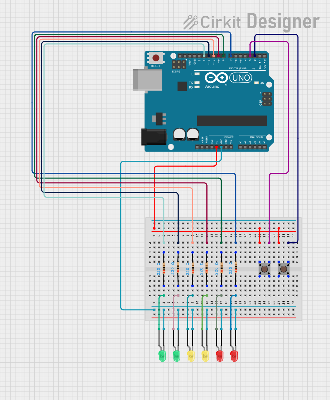
This circuit involves an Arduino UNO microcontroller, multiple LEDs of different colors, pushbuttons, and resistors. The circuit is designed to control the LEDs using the pushbuttons, with each LED connected to a specific digital pin on the Arduino. The resistors are used to limit the current flowing through the LEDs.
Component List
Arduino UNO
- Description: A microcontroller board based on the ATmega328P.
- Pins: UNUSED, IOREF, Reset, 3.3V, 5V, GND, Vin, A0, A1, A2, A3, A4, A5, SCL, SDA, AREF, D13, D12, D11, D10, D9, D8, D7, D6, D5, D4, D3, D2, D1, D0
Pushbutton
- Description: A simple pushbutton switch.
- Pins: Pin 3 (out), Pin 4 (out), Pin 1 (in), Pin 2 (in)
LED: Two Pin (red)
- Description: A red LED.
- Pins: cathode, anode
LED: Two Pin (green)
- Description: A green LED.
- Pins: cathode, anode
LED: Two Pin (yellow)
- Description: A yellow LED.
- Pins: cathode, anode
Resistor
- Description: A resistor with a resistance of 220 Ohms.
- Pins: pin1, pin2
- Properties: Resistance: 220 Ohms
Wiring Details
Arduino UNO
GND is connected to:
- cathode of green LED
- cathode of another green LED
- cathode of yellow LED
- cathode of another yellow LED
- cathode of red LED
- cathode of another red LED
5V is connected to:
- Pin 1 (in) of pushbutton
- Pin 1 (in) of another pushbutton
D12 is connected to:
- pin2 of a resistor
- anode of green LED (through the resistor)
D11 is connected to:
- pin2 of another resistor
- anode of another green LED (through the resistor)
D10 is connected to:
- pin2 of another resistor
- anode of yellow LED (through the resistor)
D9 is connected to:
- pin2 of another resistor
- anode of another yellow LED (through the resistor)
D8 is connected to:
- pin2 of another resistor
- anode of red LED (through the resistor)
D7 is connected to:
- pin2 of another resistor
- anode of another red LED (through the resistor)
D3 is connected to:
- Pin 3 (out) of pushbutton
D2 is connected to:
- Pin 3 (out) of another pushbutton
Pushbutton
Pin 1 (in) is connected to:
- 5V of Arduino UNO
Pin 3 (out) is connected to:
- D3 of Arduino UNO
Pin 1 (in) of another pushbutton is connected to:
- 5V of Arduino UNO
Pin 3 (out) of another pushbutton is connected to:
- D2 of Arduino UNO
LED: Two Pin (red)
cathode is connected to:
- GND of Arduino UNO
anode is connected to:
- pin1 of a resistor
- pin2 of the resistor is connected to D8 of Arduino UNO
cathode of another red LED is connected to:
- GND of Arduino UNO
anode of another red LED is connected to:
- pin1 of another resistor
- pin2 of the resistor is connected to D7 of Arduino UNO
LED: Two Pin (green)
cathode is connected to:
- GND of Arduino UNO
anode is connected to:
- pin1 of a resistor
- pin2 of the resistor is connected to D12 of Arduino UNO
cathode of another green LED is connected to:
- GND of Arduino UNO
anode of another green LED is connected to:
- pin1 of another resistor
- pin2 of the resistor is connected to D11 of Arduino UNO
LED: Two Pin (yellow)
cathode is connected to:
- GND of Arduino UNO
anode is connected to:
- pin1 of a resistor
- pin2 of the resistor is connected to D10 of Arduino UNO
cathode of another yellow LED is connected to:
- GND of Arduino UNO
anode of another yellow LED is connected to:
- pin1 of another resistor
- pin2 of the resistor is connected to D9 of Arduino UNO
Resistor
pin1 is connected to:
- anode of green LED
- anode of another green LED
- anode of yellow LED
- anode of another yellow LED
- anode of red LED
- anode of another red LED
pin2 is connected to:
- D12 of Arduino UNO
- D11 of Arduino UNO
- D10 of Arduino UNO
- D9 of Arduino UNO
- D8 of Arduino UNO
- D7 of Arduino UNO
Documented Code
Arduino UNO Code
void setup() {
  // put your setup code here, to run once:

}

void loop() {
  // put your main code here, to run repeatedly:

}
This code is a basic template for the Arduino UNO. The setup function is used to initialize any settings or configurations, and the loop function contains the main code that runs repeatedly.