
ESP32-Based Smart Home Automation System with 8-Channel Relay and PIR Sensor
View and Edit Project In Cirkit Designer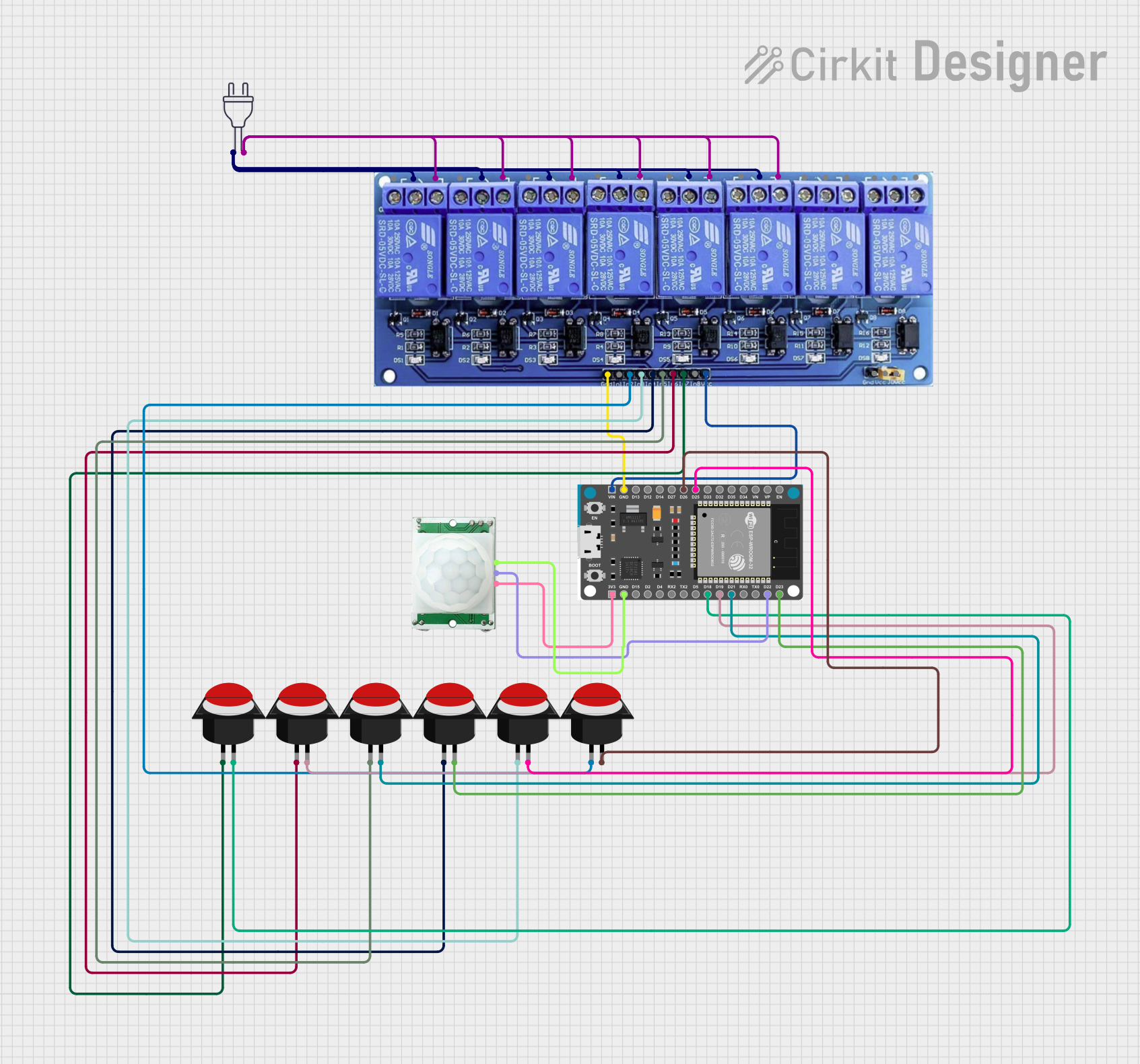
Circuit Documentation
Summary
This circuit is designed to control multiple relays using an ESP32 microcontroller. The relays are activated by push buttons and a PIR motion sensor. The circuit includes an 8-channel relay module, an ESP32 Devkit V1, several push buttons, a PIR motion sensor, and a power source. The ESP32 runs a program that reads inputs from the push buttons and the PIR sensor to control the relays, which in turn control various devices such as fans and lights.
Component List
8 Channel Relay JD-VCC
- Description: A relay module with 8 channels, used to control high voltage devices.
- Pins: JD-VCC, VCC, GND, In1, In2, In3, In4, In5, In6, In7, In8, In1_NC, IN1_COM, IN1_NO, IN2_NC, IN2_COM, IN2_NO, IN3_NC, IN3_COM, IN3_NO, IN4_NC, IN4_COM, IN4_NO, IN5_NC, IN5_COM, IN5_NO, IN6_NC, IN6_COM, IN6_NO, IN7_NC, IN7_COM, IN7_NO, IN8_NC, IN8_COM, IN8_NO
Power 220V
- Description: A 220V power source.
- Pins: Hot wire, Neutral wire
ESP32 Devkit V1
- Description: A development board for the ESP32 microcontroller.
- Pins: 3V3, GND, D15, D2, D4, RX2, TX2, D5, D18, D19, D21, RX0, TX0, D22, D23, EN, VP, VN, D34, D35, D32, D33, D25, D26, D27, D14, D12, D13, VIN
Push Button Round
- Description: A simple push button switch.
- Pins: Leg0, Leg1
PIR/Motion Sensor
- Description: A sensor that detects motion.
- Pins: GND, OUTPUT, VCC
Wiring Details
8 Channel Relay JD-VCC
- VCC: Connected to VIN of ESP32 Devkit V1
- GND: Connected to GND of ESP32 Devkit V1
- In1: Not connected
- In2: Connected to Leg0 of Push Button Round
- In3: Connected to Leg0 of Push Button Round
- In4: Connected to Leg0 of Push Button Round
- In5: Connected to Leg0 of Push Button Round
- In6: Connected to Leg0 of Push Button Round
- In7: Connected to Leg0 of Push Button Round
- In8: Not connected
- IN1_COM: Connected to Hot wire of Power 220V
- IN2_COM: Connected to Hot wire of Power 220V
- IN3_COM: Connected to Hot wire of Power 220V
- IN4_COM: Connected to Hot wire of Power 220V
- IN5_COM: Connected to Hot wire of Power 220V
- IN6_COM: Connected to Hot wire of Power 220V
- IN1_NO: Connected to Neutral wire of Power 220V
- IN2_NO: Connected to Neutral wire of Power 220V
- IN3_NO: Connected to Neutral wire of Power 220V
- IN4_NO: Connected to Neutral wire of Power 220V
- IN5_NO: Connected to Neutral wire of Power 220V
- IN6_NO: Connected to Neutral wire of Power 220V
Power 220V
- Hot wire: Connected to IN1_COM, IN2_COM, IN3_COM, IN4_COM, IN5_COM, IN6_COM of 8 Channel Relay JD-VCC
- Neutral wire: Connected to IN1_NO, IN2_NO, IN3_NO, IN4_NO, IN5_NO, IN6_NO of 8 Channel Relay JD-VCC
ESP32 Devkit V1
- VIN: Connected to VCC of 8 Channel Relay JD-VCC
- GND: Connected to GND of 8 Channel Relay JD-VCC and GND of PIR/Motion Sensor
- 3V3: Connected to VCC of PIR/Motion Sensor
- D18: Connected to Leg1 of Push Button Round
- D19: Connected to Leg1 of Push Button Round
- D21: Connected to Leg1 of Push Button Round
- D22: Connected to OUTPUT of PIR/Motion Sensor
- D23: Connected to Leg1 of Push Button Round
- D25: Connected to Leg1 of Push Button Round
- D26: Connected to Leg1 of Push Button Round
Push Button Round
- Leg0: Connected to In2, In3, In4, In5, In6, In7 of 8 Channel Relay JD-VCC
- Leg1: Connected to D18, D19, D21, D23, D25, D26 of ESP32 Devkit V1
PIR/Motion Sensor
- GND: Connected to GND of ESP32 Devkit V1
- OUTPUT: Connected to D22 of ESP32 Devkit V1
- VCC: Connected to 3V3 of ESP32 Devkit V1
Code Documentation
#include <Arduino.h>

// Define pin connections
#define PIR_SENSOR_PIN 22
#define FAN1_RELAY_PIN 18
#define FAN2_RELAY_PIN 19
#define LIGHT1_RELAY_PIN 21
#define LIGHT2_RELAY_PIN 23
#define LIGHT3_RELAY_PIN 25
#define LIGHT4_RELAY_PIN 26

#define SWITCH1_PIN 18
#define SWITCH2_PIN 19
#define SWITCH3_PIN 21
#define SWITCH4_PIN 23
#define SWITCH5_PIN 25
#define SWITCH6_PIN 26

// Variables to store the state of the relays
bool fan1State = false;
bool fan2State = false;
bool light1State = false;
bool light2State = false;
bool light3State = false;
bool light4State = false;

void setup() {
  // Initialize serial communication
  Serial.begin(115200);

  // Initialize PIR sensor pin
  pinMode(PIR_SENSOR_PIN, INPUT);

  // Initialize relay pins
  pinMode(FAN1_RELAY_PIN, OUTPUT);
  pinMode(FAN2_RELAY_PIN, OUTPUT);
  pinMode(LIGHT1_RELAY_PIN, OUTPUT);
  pinMode(LIGHT2_RELAY_PIN, OUTPUT);
  pinMode(LIGHT3_RELAY_PIN, OUTPUT);
  pinMode(LIGHT4_RELAY_PIN, OUTPUT);

  // Initialize switch pins
  pinMode(SWITCH1_PIN, INPUT_PULLUP);
  pinMode(SWITCH2_PIN, INPUT_PULLUP);
  pinMode(SWITCH3_PIN, INPUT_PULLUP);
  pinMode(SWITCH4_PIN, INPUT_PULLUP);
  pinMode(SWITCH5_PIN, INPUT_PULLUP);
  pinMode(SWITCH6_PIN, INPUT_PULLUP);

  // Turn off all relays initially
  digitalWrite(FAN1_RELAY_PIN, LOW);
  digitalWrite(FAN2_RELAY_PIN, LOW);
  digitalWrite(LIGHT1_RELAY_PIN, LOW);
  digitalWrite(LIGHT2_RELAY_PIN, LOW);
  digitalWrite(LIGHT3_RELAY_PIN, LOW);
  digitalWrite(LIGHT4_RELAY_PIN, LOW);
}

void loop() {
  // Read PIR sensor value
  int pirValue = digitalRead(PIR_SENSOR_PIN);

  // If motion is detected, turn on fans and lights
  if (pirValue == HIGH) {
    fan1State = true;
    fan2State = true;
    light1State = true;
    light2State = true;
    light3State = true;
    light4State = true;
  }

  // Read switch states and toggle corresponding relays
  if (digitalRead(SWITCH1_PIN) == LOW) {
    fan1State = !fan1State;
    delay(200); // Debounce delay
  }
  if (digitalRead(SWITCH2_PIN) == LOW) {
    fan2State = !fan2State;
    delay(200); // Debounce delay
  }
  if (digitalRead(SWITCH3_PIN)