Cirkit Designer
Your all-in-one circuit design IDE
Home /
Project Documentation
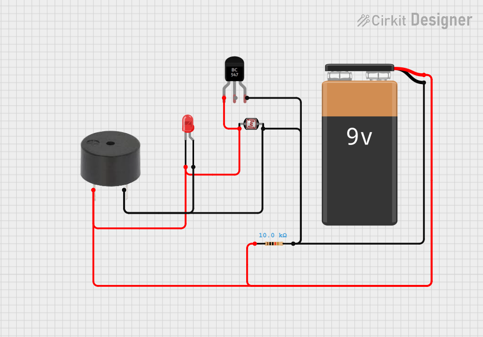
Battery-Powered Light-Activated Alarm with BC547 Transistor and Photocell
Circuit Documentation
Summary
This document provides a detailed overview of a simple electronic circuit that includes a 9V battery, a BC547 transistor, a photocell (LDR), a resistor, a buzzer, and a red LED. The circuit is designed to activate the buzzer and LED based on the light intensity detected by the photocell.
Component List
9V Battery
- Description: Provides the power supply for the circuit.
- Pins: +, -
BC547 Transistor
- Description: A general-purpose NPN transistor used for switching and amplification.
- Pins: Collector, Base, Emitter
Photocell (LDR)
- Description: A light-dependent resistor that changes its resistance based on the light intensity.
- Pins: pin 0, pin 1
Resistor
- Description: Limits the current flow in the circuit.
- Pins: pin1, pin2
- Properties:
- Resistance: 10,000 Ohms
Buzzer
- Description: Produces sound when activated.
- Pins: PIN, GND
LED: Two Pin (red)
- Description: Emits red light when current flows through it.
- Pins: cathode, anode
Wiring Details
9V Battery
+ Pin:
- Connected to the Collector of the BC547 Transistor
- Connected to pin 0 of the Photocell (LDR)
- Connected to the PIN of the Buzzer
- Connected to pin1 of the Resistor
- Connected to the cathode of the LED
- Pin:
- Connected to the Emitter of the BC547 Transistor
- Connected to pin 1 of the Photocell (LDR)
- Connected to the GND of the Buzzer
- Connected to pin2 of the Resistor
- Connected to the anode of the LED
BC547 Transistor
Collector:
- Connected to the + pin of the 9V Battery
- Connected to pin 0 of the Photocell (LDR)
- Connected to the PIN of the Buzzer
- Connected to pin1 of the Resistor
- Connected to the cathode of the LED
Emitter:
- Connected to the - pin of the 9V Battery
- Connected to pin 1 of the Photocell (LDR)
- Connected to the GND of the Buzzer
- Connected to pin2 of the Resistor
- Connected to the anode of the LED
Photocell (LDR)
pin 0:
- Connected to the + pin of the 9V Battery
- Connected to the Collector of the BC547 Transistor
- Connected to the PIN of the Buzzer
- Connected to pin1 of the Resistor
- Connected to the cathode of the LED
pin 1:
- Connected to the - pin of the 9V Battery
- Connected to the Emitter of the BC547 Transistor
- Connected to the GND of the Buzzer
- Connected to pin2 of the Resistor
- Connected to the anode of the LED
Resistor
pin1:
- Connected to the + pin of the 9V Battery
- Connected to the Collector of the BC547 Transistor
- Connected to pin 0 of the Photocell (LDR)
- Connected to the PIN of the Buzzer
- Connected to the cathode of the LED
pin2:
- Connected to the - pin of the 9V Battery
- Connected to the Emitter of the BC547 Transistor
- Connected to pin 1 of the Photocell (LDR)
- Connected to the GND of the Buzzer
- Connected to the anode of the LED
Buzzer
PIN:
- Connected to the + pin of the 9V Battery
- Connected to the Collector of the BC547 Transistor
- Connected to pin 0 of the Photocell (LDR)
- Connected to pin1 of the Resistor
- Connected to the cathode of the LED
GND:
- Connected to the - pin of the 9V Battery
- Connected to the Emitter of the BC547 Transistor
- Connected to pin 1 of the Photocell (LDR)
- Connected to pin2 of the Resistor
- Connected to the anode of the LED
LED: Two Pin (red)
cathode:
- Connected to the + pin of the 9V Battery
- Connected to the Collector of the BC547 Transistor
- Connected to pin 0 of the Photocell (LDR)
- Connected to the PIN of the Buzzer
- Connected to pin1 of the Resistor
anode:
- Connected to the - pin of the 9V Battery
- Connected to the Emitter of the BC547 Transistor
- Connected to pin 1 of the Photocell (LDR)
- Connected to the GND of the Buzzer
- Connected to pin2 of the Resistor
Code
There is no microcontroller code associated with this circuit.