Cirkit Designer
Your all-in-one circuit design IDE
Home /
Project Documentation
Arduino Pro Mini Based CAN Bus Interface with OLED Display
Circuit Documentation
Summary
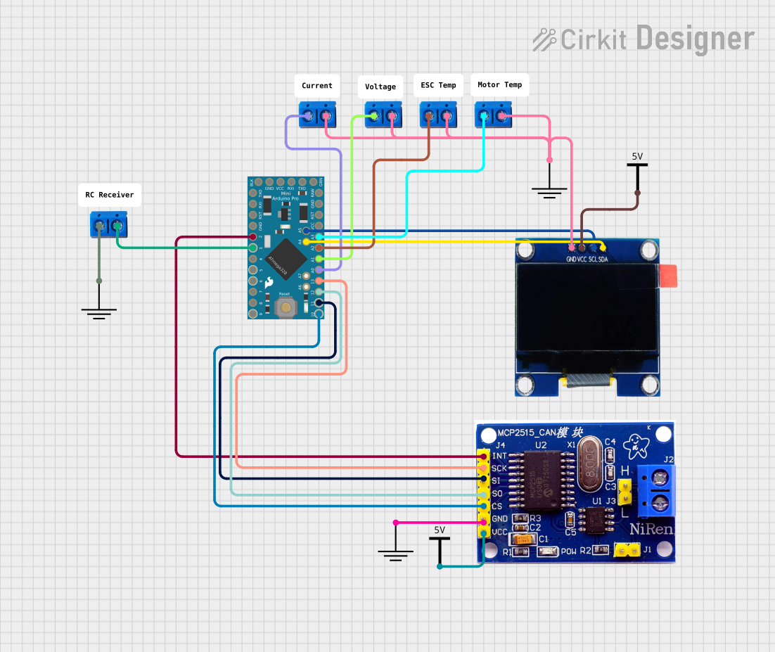
This circuit integrates an Arduino Pro Mini with an OLED 1.3" display and an MCP2515 CAN Bus controller. The Arduino Pro Mini serves as the central microcontroller, interfacing with the OLED display via I2C communication and with the MCP2515 for CAN network communication. The circuit also includes several terminal PCBs for external connections and power distribution components (Vcc and GND).
Component List
Arduino Pro Mini
- Description: A compact microcontroller board based on the ATmega328 (Arduino Nano 3.x) or ATmega168 (Arduino Nano 2.x).
- Pins: DTR, TXO, RXI, VCC, GND, A4, A5, RAW, RESET, A3, A2, A1, A0, SCK, MISO, MOSI, D10, D9, D8, D7, D6, D5, D4, D3, D2
OLED 1.3"
- Description: A small OLED display for visual output.
- Pins: GND, VCC, SCL, SDA
MCP2515
- Description: A stand-alone Controller Area Network (CAN) controller that implements the CAN specification, version 2.0B.
- Pins: INT, SCK, SI, SO, CS, GND, VCC, H, L
Terminal PCB 2 Pin
- Description: A simple two-pin terminal block for making external connections.
- Pins: Pin A, Pin B
GND
- Description: Ground reference for the circuit.
- Pins: GND
Vcc
- Description: Power supply for the circuit components.
- Pins: Vcc
Comment
- Description: A placeholder for comments within the circuit design, not a physical component.
Wiring Details
Arduino Pro Mini
- A4 connected to OLED SDA
- A5 connected to OLED SCL
- A3 connected to Terminal PCB 2 Pin (Instance 1)
- A2 connected to Terminal PCB 2 Pin (Instance 2)
- A1 connected to Terminal PCB 2 Pin (Instance 3)
- A0 connected to Terminal PCB 2 Pin (Instance 4)
- SCK connected to MCP2515 SCK
- MISO connected to MCP2515 SO
- MOSI connected to MCP2515 SI
- D10 connected to MCP2515 CS
- D3 connected to Terminal PCB 2 Pin (Instance 5)
- D2 connected to MCP2515 INT
OLED 1.3"
- SDA connected to Arduino Pro Mini A4
- SCL connected to Arduino Pro Mini A5
- GND connected to common ground net
- VCC connected to Vcc
MCP2515
- SCK connected to Arduino Pro Mini SCK
- SO connected to Arduino Pro Mini MISO
- SI connected to Arduino Pro Mini MOSI
- CS connected to Arduino Pro Mini D10
- INT connected to Arduino Pro Mini D2
- GND connected to common ground net
- VCC connected to Vcc
Terminal PCB 2 Pin (Instances 1 to 4)
- Pin A connected to respective Arduino Pro Mini analog pins (A3, A2, A1, A0)
- Pin B connected to common ground net
Terminal PCB 2 Pin (Instance 5)
- Pin A connected to Arduino Pro Mini D3
- Pin B connected to common ground net
GND
- All GND pins connected to common ground net
Vcc
- All Vcc pins connected to power supply net
Documented Code
Arduino Pro Mini Code (sketch.ino)
void setup() {
  // put your setup code here, to run once:

}

void loop() {
  // put your main code here, to run repeatedly:

}
Additional Notes
- The code provided for the Arduino Pro Mini is a template with empty setup and loop functions. This code needs to be populated with the logic for initializing and managing the OLED display and MCP2515 CAN controller.
- The documentation file associated with the microcontroller is empty and can be used for further detailed documentation of the code logic and functionality.