Cirkit Designer
Your all-in-one circuit design IDE
Home /
Project Documentation
Arduino UNO and HC-05 Bluetooth Module Controlled LED
Circuit Documentation
Summary
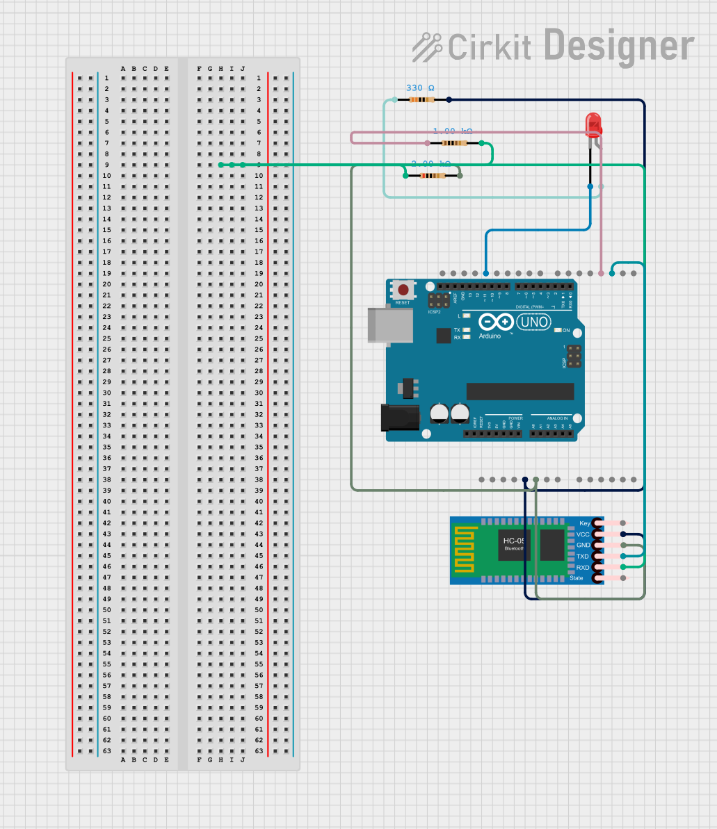
This circuit is designed to control an LED using an Arduino UNO and an HC-05 Bluetooth module. The LED can be turned on or off based on commands received via Bluetooth. The circuit includes resistors to limit current and ensure proper operation of the components.
Component List
HC-05 Bluetooth Module
- Description: A Bluetooth module used for wireless communication.
- Pins: Key, VCC, TXD, RXD, State, GND
Resistor (1k Ohms)
- Description: A resistor with a resistance of 1000 Ohms.
- Pins: pin1, pin2
Resistor (2k Ohms)
- Description: A resistor with a resistance of 2000 Ohms.
- Pins: pin1, pin2
Resistor (330 Ohms)
- Description: A resistor with a resistance of 330 Ohms.
- Pins: pin1, pin2
LED: Two Pin (red)
- Description: A red LED with two pins.
- Pins: cathode, anode
Arduino UNO
- Description: A microcontroller board based on the ATmega328P.
- Pins: UNUSED, IOREF, Reset, 3.3V, 5V, GND, Vin, A0, A1, A2, A3, A4, A5, SCL, SDA, AREF, D13, D12, D11, D10, D9, D8, D7, D6, D5, D4, D3, D2, D1, D0
Wiring Details
HC-05 Bluetooth Module
- VCC: Connected to the 5V pin of the Arduino UNO through a 330 Ohm resistor.
- TXD: Connected to pin D2 of the Arduino UNO.
- RXD: Connected to pin1 of a 2k Ohm resistor, which is then connected to pin2 of a 1k Ohm resistor.
- GND: Connected to the GND pin of the Arduino UNO through pin2 of the 2k Ohm resistor.
Resistor (1k Ohms)
- pin1: Connected to pin D3 of the Arduino UNO.
- pin2: Connected to pin1 of the 2k Ohm resistor.
Resistor (2k Ohms)
- pin1: Connected to the RXD pin of the HC-05 Bluetooth Module.
- pin2: Connected to the GND pin of the HC-05 Bluetooth Module and the GND pin of the Arduino UNO.
Resistor (330 Ohms)
- pin1: Connected to the anode of the LED.
- pin2: Connected to the 5V pin of the Arduino UNO and the VCC pin of the HC-05 Bluetooth Module.
LED: Two Pin (red)
- anode: Connected to pin1 of the 330 Ohm resistor.
- cathode: Connected to pin D13 of the Arduino UNO.
Arduino UNO
- 5V: Connected to pin2 of the 330 Ohm resistor and the VCC pin of the HC-05 Bluetooth Module.
- GND: Connected to pin2 of the 2k Ohm resistor and the GND pin of the HC-05 Bluetooth Module.
- D2: Connected to the TXD pin of the HC-05 Bluetooth Module.
- D3: Connected to pin1 of the 1k Ohm resistor.
- D13: Connected to the cathode of the LED.
Documented Code
#include <SoftwareSerial.h>

#define ledpin 13   // LED connected to pin 13

SoftwareSerial bt(2, 3);  // (Rx, Tx) Pins 2 and 3 for SoftwareSerial

byte state = '2';  // Default state

void setup() {
  delay(1000);  // Wait for Bluetooth to initialize
  pinMode(ledpin, OUTPUT);  // Set LED pin as output
  digitalWrite(ledpin, LOW);  // Turn LED off initially
  bt.begin(9600);  // Start Bluetooth communication at 9600 baud rate
}

void loop() {
  if (bt.available()) {  // If Bluetooth data is available
    state = bt.read();  // Read the incoming byte

    if (state == '0') {  // If received '0', turn LED off
      digitalWrite(ledpin, LOW);
      bt.write("LED OFF\n");
      state = '2';  // Reset state to avoid continuous action
    }
    else if (state == '1') {  // If received '1', turn LED on
      digitalWrite(ledpin, HIGH);
      bt.write("LED ON\n");
      state = '2';  // Reset state
    }
  }

  delay(500);  // Add a short delay to prevent overloading the serial
}
This code initializes the Bluetooth module and sets up the LED pin. It listens for incoming Bluetooth data and turns the LED on or off based on the received commands ('0' for off and '1' for on).