
Circuit Documentation
Summary
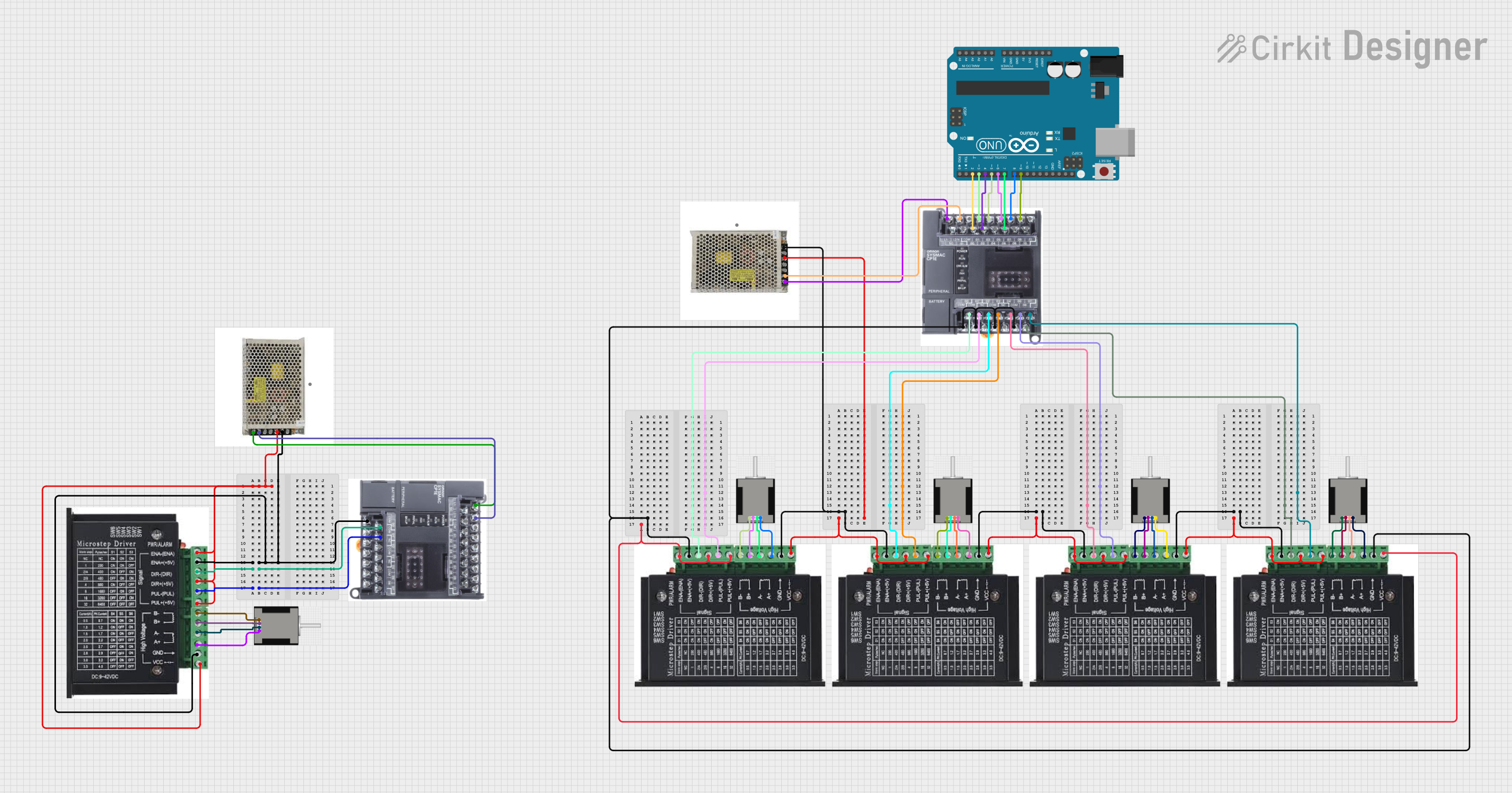
This document provides a detailed overview of a circuit that includes multiple NEMA 17 stepper motors, stepper drivers, a 24V DC power supply, a PLC, and an Arduino UNO. The circuit is designed to control the stepper motors using the PLC and Arduino UNO, with power supplied by the 24V DC power supply.
Component List
NEMA 17 HS4401
- Description: Stepper motor
- Pins: RED (B2), BLACK (B1), BLUE (A2), GREEN (A1)
Stepper Driver
- Description: Driver for stepper motors
- Pins: ENA, ENA -, DIR-, DIR+, PUL-, PUL +, B-, B+, A-, A+, GND, VCC
Power Supply 24 VDC
- Description: 24V DC power supply
- Pins: L, N, E, V+, V-
PLC
- Description: Programmable Logic Controller
- Pins: L1, L2/N, GND, COM, 00, 01, 02, 03, 04, 05, 06, 07, 08, 09, 10, 11, COM1, COM2, NC, COM3, COM4
Arduino UNO
- Description: Microcontroller board
- Pins: UNUSED, IOREF, Reset, 3.3V, 5V, GND, Vin, A0, A1, A2, A3, A4, A5, SCL, SDA, AREF, D13, D12, D11, D10, D9, D8, D7, D6, D5, D4, D3, D2, D1, D0
Wiring Details
NEMA 17 HS4401
- RED (B2) connected to Stepper Driver B-
- BLACK (B1) connected to Stepper Driver B+
- BLUE (A2) connected to Stepper Driver A-
- GREEN (A1) connected to Stepper Driver A+
Stepper Driver
- ENA connected to Power Supply 24 VDC V+
- ENA - connected to Power Supply 24 VDC V-
- DIR- connected to PLC 00
- DIR+ connected to Power Supply 24 VDC V+
- PUL- connected to PLC 01
- PUL + connected to Power Supply 24 VDC V+
- B- connected to NEMA 17 HS4401 RED (B2)
- B+ connected to NEMA 17 HS4401 BLACK (B1)
- A- connected to NEMA 17 HS4401 BLUE (A2)
- A+ connected to NEMA 17 HS4401 GREEN (A1)
- GND connected to Power Supply 24 VDC V-
- VCC connected to Power Supply 24 VDC V+
Power Supply 24 VDC
- L connected to PLC L1
- N connected to PLC L2/N
- E not connected
- V+ connected to Stepper Driver ENA, DIR+, PUL +, VCC
- V- connected to Stepper Driver ENA -, GND
PLC
- L1 connected to Power Supply 24 VDC L
- L2/N connected to Power Supply 24 VDC N
- GND not connected
- COM not connected
- 00 connected to Stepper Driver DIR-
- 01 connected to Stepper Driver PUL-
- 02 connected to Arduino UNO D4
- 03 connected to Arduino UNO D5
- 04 connected to Stepper Driver DIR-
- 05 connected to Stepper Driver PUL-
- 06 connected to Stepper Driver DIR-
- 07 connected to Stepper Driver PUL-
- 08 not connected
- 09 connected to Arduino UNO D9
- 10 not connected
- 11 not connected
- COM1 connected to Power Supply 24 VDC V-
- COM2 connected to Power Supply 24 VDC V-
- NC not connected
- COM3 connected to Power Supply 24 VDC V-
- COM4 connected to Power Supply 24 VDC V-
Arduino UNO
- D2 connected to PLC 00
- D3 connected to PLC 01
- D4 connected to PLC 02
- D5 connected to PLC 03
- D6 connected to PLC 05
- D7 connected to PLC 06
- D8 connected to PLC 07
- D9 connected to PLC 09
Documented Code
Arduino UNO Code (sketch.ino)
void setup() {
  // put your setup code here, to run once:

}

void loop() {
  // put your main code here, to run repeatedly:

}
Additional Documentation (documentation.txt)
This document provides a comprehensive overview of the circuit, including a summary, component list, wiring details, and documented code.