Raspberry Pi-Controlled LED Lighting System with Time-Based Color Switching
Circuit Documentation
Summary
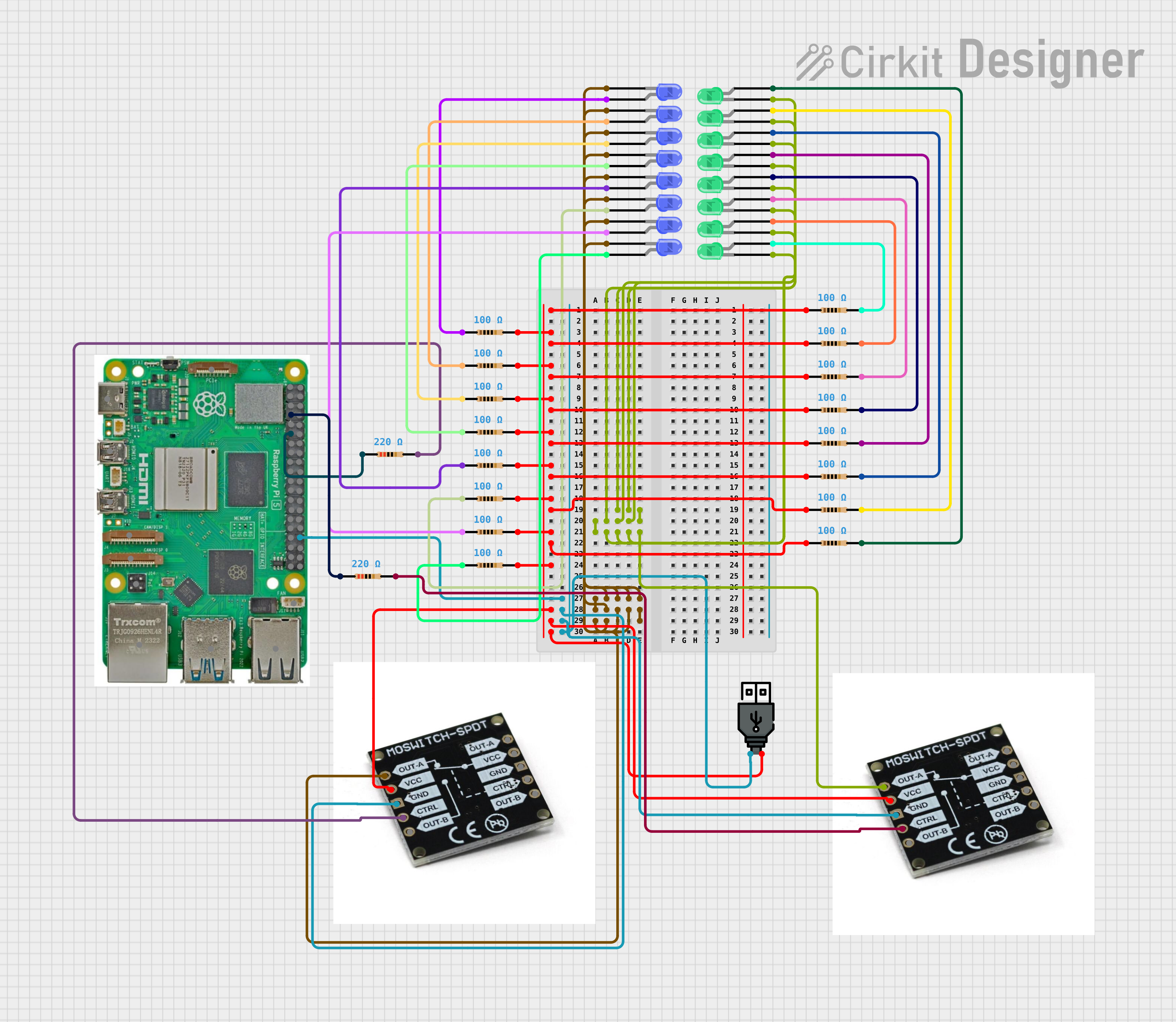
The circuit in question appears to be a lighting control system utilizing a Raspberry Pi 5 as the central microcontroller. The system is designed to control two sets of LEDs (blue and green) through MOSFET switches. The LEDs are connected in series with resistors to limit the current. The Raspberry Pi 5 controls the MOSFETs, which in turn switch the LEDs on and off. The blue LEDs are programmed to turn on during a specific time window, while the green LEDs are turned on indefinitely. The circuit is powered by a USB power source.
Component List
Resistors
- 100 Ohm Resistors: Used to limit the current through the LEDs, ensuring they operate within safe parameters.
- 220 Ohm Resistors: Used to limit the current through the LEDs, ensuring they operate within safe parameters.
LEDs
- Blue LEDs: Indicators or for aesthetic purposes, controlled based on a time schedule.
- Green LEDs: Indicators or for aesthetic purposes, always on when the system is powered.
MOSFET Switch SPDT
- MOSFET Switches: Used to control the power to the LED arrays. They act as electronic switches that are controlled by the Raspberry Pi's GPIO pins.
Raspberry Pi 5
- Microcontroller: The brain of the circuit, it runs the control software that determines when the LEDs are turned on and off.
USB Power
- Power Source: Provides the necessary power to the circuit.
Wiring Details
Resistors
- 100 Ohm Resistors: Each resistor has two pins, pin1 and pin2. Pin1 of each resistor is connected to a common voltage line, while pin2 is connected to an LED or another resistor in series.
- 220 Ohm Resistors: Each resistor has two pins, pin1 and pin2. Pin1 of each resistor is connected to a GPIO pin on the Raspberry Pi, while pin2 is connected to the control pin of a MOSFET.
LEDs
- Blue LEDs: Each LED has a cathode and an anode. The cathode of each LED is connected to the output of a MOSFET, while the anode is connected to a 100 Ohm resistor.
- Green LEDs: Each LED has a cathode and an anode. The cathode of each LED is connected to the output of a MOSFET, while the anode is connected to a 100 Ohm resistor.
MOSFET Switch SPDT
- MOSFET Switches: Each MOSFET has five pins: OUT-A, VCC, GND, CTRL, and OUT-B. The VCC pins of both MOSFETs are connected to the positive terminal of the USB power source. The GND pins are connected to the ground terminal of the USB power source and the Raspberry Pi. The CTRL pins are connected to the GPIO pins of the Raspberry Pi through 220 Ohm resistors.
Raspberry Pi 5
- Microcontroller: The Raspberry Pi's GPIO pins are used to control the MOSFETs. GPIO 4 is connected to the control pin of the MOSFET for green LEDs, and GPIO 17 is connected to the control pin of the MOSFET for blue LEDs.
USB Power
- Power Source: The positive terminal is connected to the VCC pins of the MOSFETs, and the negative terminal is connected to the ground of the circuit.
Documented Code
import RPi.GPIO as GPIO
import time
from datetime import datetime

# Pin definitions
GREEN_LED_CTRL_PIN = 4  # GPIO pin connected to the control pin of the MOSFET for green LEDs
BLUE_LED_CTRL_PIN = 17   # GPIO pin connected to the control pin of the MOSFET for blue LEDs

# Setup
GPIO.setmode(GPIO.BCM)
GPIO.setup(GREEN_LED_CTRL_PIN, GPIO.OUT)
GPIO.setup(BLUE_LED_CTRL_PIN, GPIO.OUT)

# Turn on green LEDs
GPIO.output(GREEN_LED_CTRL_PIN, GPIO.HIGH)

try:
    while True:
        current_time = datetime.now().time()
        if current_time >= datetime.strptime("18:00", "%H:%M").time() and current_time <= datetime.strptime("22:00", "%H:%M").time():
            GPIO.output(BLUE_LED_CTRL_PIN, GPIO.HIGH)  # Turn on blue LEDs
        else:
            GPIO.output(BLUE_LED_CTRL_PIN, GPIO.LOW)   # Turn off blue LEDs
        time.sleep(60)  # Check every minute
except KeyboardInterrupt:
    pass
finally:
    GPIO.cleanup()
This code is designed to run on the Raspberry Pi 5. It sets up two GPIO pins as outputs to control the MOSFETs that power the green and blue LEDs. The green LEDs are turned on as soon as the program starts. The blue LEDs are controlled based on the current time: they are turned on between 18:00 and 22:00 and turned off otherwise. The time is checked every minute to update the state of the blue LEDs.