
STM32H7-Based Multi-Sensor Monitoring System with GSM Alert and LCD Display
View and Edit Project In Cirkit Designer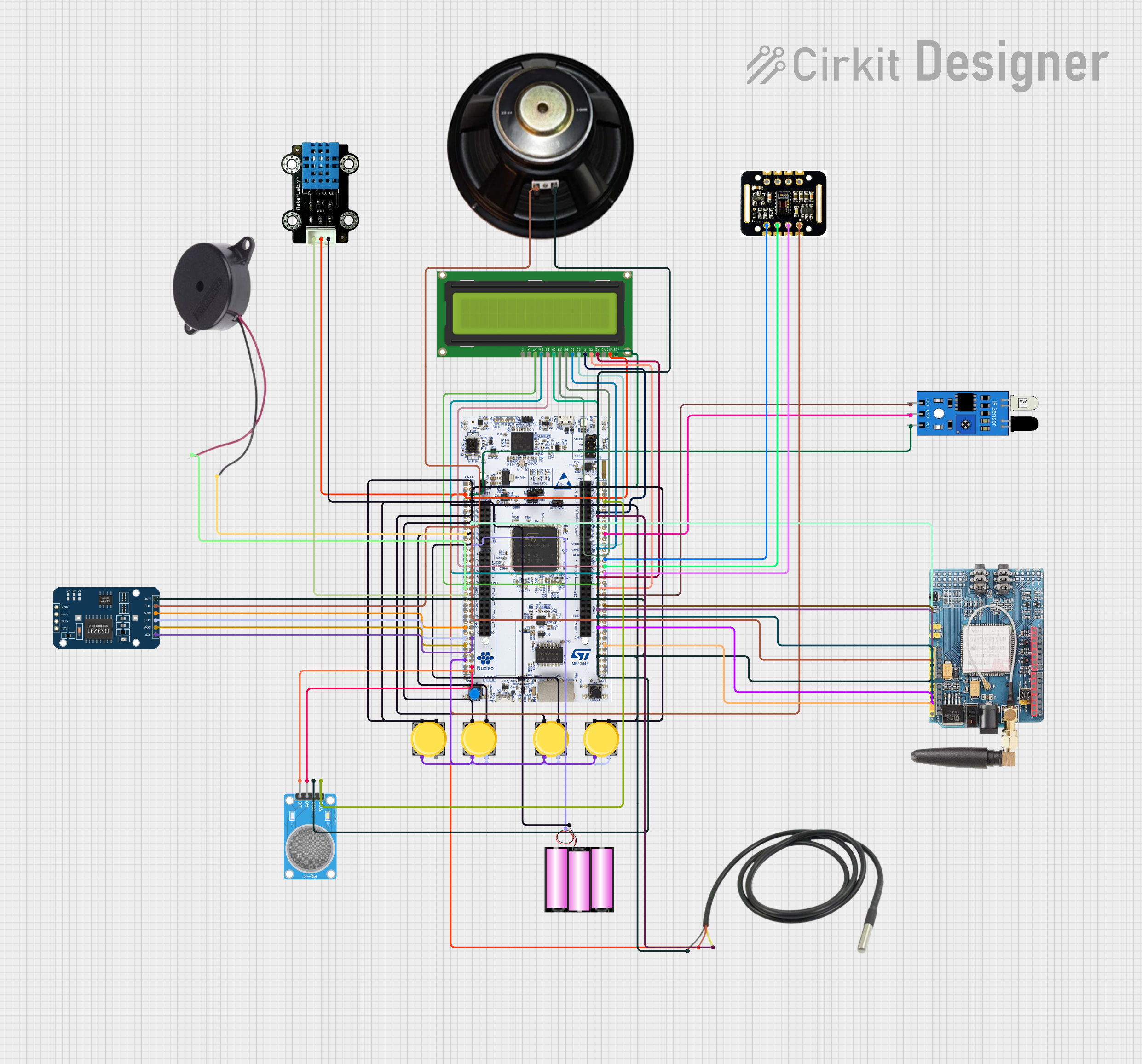
Circuit Documentation
Summary
The circuit in question is a multifunctional embedded system designed around the STM32H7 microcontroller. It interfaces with a variety of sensors and modules to perform tasks such as temperature and humidity measurement, real-time clock tracking, gas detection, heart rate and blood oxygen level monitoring, and user interaction through pushbuttons and an LCD display. The system is powered by a 12V battery and includes communication capabilities through a GSM module. The circuit is designed to read sensor data, process it, and display the results on an LCD screen, as well as send alerts via GSM when certain conditions are met.
Component List
Battery 12V
A power source for the circuit providing a 12-volt supply.
Pushbutton
A momentary switch that allows user input when pressed.
Buzzer
An audio signaling device that can emit a tone when powered.
Speaker
A transducer that converts electrical signals into audible sound.
DS3231 RTC
A real-time clock module for keeping track of the current time and date.
IR Sensor
An infrared sensor used for proximity or motion detection.
MKE-S14 DHT11 Temperature and Humidity Sensor
A sensor that measures ambient temperature and humidity.
GSM SIM900
A GSM/GPRS module for cellular communication.
MQ-2 Sensor
A gas sensor used for detecting levels of combustible gases.
MAX30102 HR + SpO2 Sensor
A sensor for measuring heart rate and blood oxygen levels.
Temperature Sensor
A sensor for measuring temperature.
LCD Display 16x2
A liquid crystal display capable of showing 16 characters per line on 2 lines.
STM32H7 Microcontroller
A high-performance microcontroller that serves as the central processing unit for the circuit.
Wiring Details
Battery 12V
+to STM32H7 VIN-to circuit ground
Pushbuttons
- Pin 2 to circuit ground
- Pin 4 to circuit ground
- Pin 1 to STM32H7 PD0 (shared among all pushbuttons)
- Pin 3 to STM32H7 PG12 (shared among all pushbuttons)
Buzzer
- POSITIVE to STM32H7 PD4
- NEGATIVE to circuit ground
Speaker
+to 5V supply from STM32H7-to circuit ground
DS3231 RTC
- 32K to STM32H7 PG1
- SQW to STM32H7 PG0
- SCL to STM32H7 PD0
- SDA to STM32H7 PF0
- VCC to 5V supply from STM32H7
- GND to circuit ground
IR Sensor
- out to STM32H7 PD13
- gnd to circuit ground
- vcc to STM32H7 E5V
MKE-S14 DHT11 Temperature and Humidity Sensor
- SIG to STM32H7 PD5
- 5V to STM32H7 VDD
- GND to circuit ground
GSM SIM900
- 3.3V to STM32H7 3V3
- 5V to 5V supply from STM32H7
- GND to circuit ground
- A0 to STM32H7 PD14
- A1 to STM32H7 PE10
- A2 to STM32H7 PE12
- A3 to STM32H7 PE15
- A4 to STM32H7 PF15
MQ-2 Sensor
- VCC to STM32H7 U5V
- GND to circuit ground
- A0 to STM32H7 PG13
- D0 to STM32H7 PG11
MAX30102 HR + SpO2 Sensor
- INT not connected
- IRD not connected
- RD not connected
- GND to STM32H7 PB13
- SCL to STM32H7 AGND
- SDA to STM32H7 PC4
- VIN to 5V supply from STM32H7
Temperature Sensor
- Temp GND Black to circuit ground
- Temp VDD Red to STM32H7 VDD
- Temp DQ Data Yellow to STM32H7 PA6
LCD Display 16x2
- LEDK to circuit ground
- LEDA to 5V supply from STM32H7
- DB7 to STM32H7 PA3
- DB6 to STM32H7 PA10
- DB5 to STM32H7 PB3
- DB4 to STM32H7 PB5
- DB3 to STM32H7 PB4
- DB2 to STM32H7 PB4
- DB1 to STM32H7 PB10
- DB0 to STM32H7 PA8
- E to STM32H7 PA5
- RW to circuit ground
- RS to STM32H7 PA2
- VO not connected
- VDD to STM32H7 VDD
- VSS to STM32H7 E5V
STM32H7 Microcontroller
- VDD to 5V supply
- E5V to IR Sensor vcc and LCD Display VSS
- GND to circuit ground (common for multiple components)
- 3V3 to GSM SIM900 3.3V
- PD4 to Buzzer POSITIVE
- PD5 to DHT11 SIG
- PF0 to DS3231 RTC SDA
- PD0 to DS3231 RTC SCL and Pushbuttons Pin 1
- PG0 to DS3231 RTC SQW
- PG12 to Pushbuttons Pin 3
- 5V to DS3231 RTC VCC, Speaker +, GSM SIM900 5V, MAX30102 HR + SpO2 Sensor VIN
- VIN to Battery 12V +
- PG11 to MQ-2 SENSOR D0
- PG13 to MQ-2 SENSOR A0
- PG1 to DS3231 RTC 32K
- U5V to MQ-2 SENSOR VCC
- PA5 to LCD Display E
- PA6 to Temperature Sensor Temp DQ Data Yellow
- PA8 to LCD Display DB0
- PB10 to LCD Display DB1
- PB4 to LCD Display DB2 and DB3
- PB5 to LCD Display DB4
- PB13 to MAX30102 HR + SpO2 Sensor GND
- PB3 to LCD Display DB5
- AGND to MAX30102 HR + SpO2 Sensor SCL
- PA10 to LCD Display DB6
- PA2 to LCD Display RS
- PC4 to MAX30102 HR + SpO2 Sensor SDA
- PA3 to LCD Display DB7
- PD13 to IR Sensor out
- PE10 to GSM SIM900 A1
- PE12 to GSM SIM900 A2
- PE15 to GSM SIM900 A3
- PD14 to GSM SIM900 A0
- PF15 to GSM SIM900 A4
Documented Code
#include "stm32f1xx_hal.h"

// Function prototypes
void SystemClock_Config(void);
void init_GPIO(void);
void init_I2C(void);
void init_UART(void);
void read_DHT11(void);
void read_RTC(void);
void read_PulseOximeter(void);
void read_BodyTemp(void);
void check_SmokeDetector(void);
void handle_Buttons(void);
void send_GSM_Alert(void);
void update_LCD(void);

int main(void) {
    HAL_Init();
    SystemClock_Config();
    init_GPIO();
    init_I2C();
    init_UART();

    while (1) {
        read_DHT11();
        read_RTC();
        read_PulseOximeter();
        read_BodyTemp();
        check_SmokeDetector();
        handle_Buttons();
        update_LCD();
        HAL_Delay(1000); // Delay for 1 second
    }
}

void init_GPIO(void) {
    // Initialize GPIO pins for all components
}

void init_I2C(void) {
    // Initialize I2C communication
}

void init_UART(void) {
    // Initialize UART communication
}

void read_DHT11(void) {
    // Read data from DHT11 sensor
}

void read_RTC(void) {
    // Read time from RTC Module
}

void read_PulseOximeter(void) {
    // Read data from Pulse Oximeter
}

void read_BodyTemp(void) {
    // Read data from Body Temperature Sensor
}

void check_SmokeDetector(void) {
    // Check smoke detector status
}

void handle_Buttons(void) {
    // Handle push button inputs
}

void send_GSM_Alert(void) {
    // Send alert via GSM Module
}

void update_LCD(void) {
    // Update the LCD display with new data
}

void SystemClock_Config(void) {
    // Configure the system clock
}
This code provides the basic structure for the embedded system's operation. It includes initialization functions for the GPIO pins, I2C and UART communication, and functions to read from the various sensors. The main function contains an infinite loop that continuously reads sensor data, checks the status of the smoke detector, handles button inputs, updates the LCD display, and sends alerts via the GSM module. The actual implementation of these functions will depend on the specific hardware connections and the desired behavior of the system.