
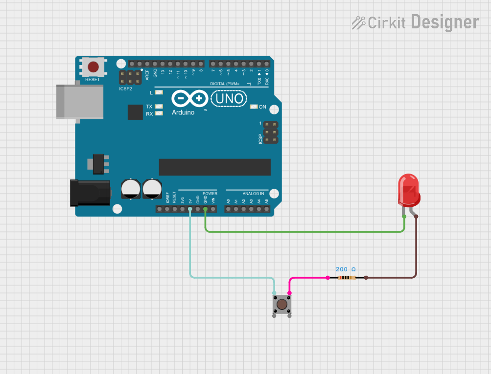
Circuit Documentation
Summary
This circuit consists of an Arduino UNO microcontroller, a pushbutton, a red LED, and a resistor. The pushbutton is used to control the state of the LED, which lights up when the button is pressed. The resistor is used to limit the current flowing through the LED, ensuring safe operation.
Component List
Arduino UNO
- Description: A microcontroller board based on the ATmega328P.
- Purpose: Acts as the main control unit for the circuit, processing inputs from the pushbutton and controlling the LED.
Pushbutton
- Description: A simple mechanical switch that can be pressed to make or break a connection.
- Purpose: Used to provide a user input to the Arduino, allowing the user to control the LED.
LED Two Pin (Red)
- Description: A two-pin light-emitting diode that emits red light when current flows through it.
- Purpose: Provides visual feedback to the user, indicating the state of the circuit (on/off).
Resistor
- Description: An electronic component that resists the flow of current, creating a voltage drop.
- Purpose: Limits the current flowing through the LED to prevent damage.
Wiring Details
Arduino UNO
5V: Connected to Pin 1 (in) of the Pushbutton.
GND: Connected to Cathode of the LED.
Pushbutton
Pin 1 (in): Connected to 5V of the Arduino UNO.
Pin 3 (out): Connected to pin1 of the Resistor.
LED Two Pin (Red)
Cathode: Connected to GND of the Arduino UNO.
Anode: Connected to pin2 of the Resistor.
Resistor
pin1: Connected to Pin 3 (out) of the Pushbutton.
pin2: Connected to Anode of the LED.
Documented Code
Arduino UNO Code
void setup() {
  // put your setup code here, to run once:

}

void loop() {
  // put your main code here, to run repeatedly:

}
Documentation Code
This documentation provides a comprehensive overview of the circuit, detailing each component, its purpose, and the wiring connections. The code section includes the basic structure for the Arduino UNO, ready for further development.