
Arduino Mega 2560-Based Smart Door Lock System with RFID, Fingerprint, and Wi-Fi Connectivity
View and Edit Project In Cirkit Designer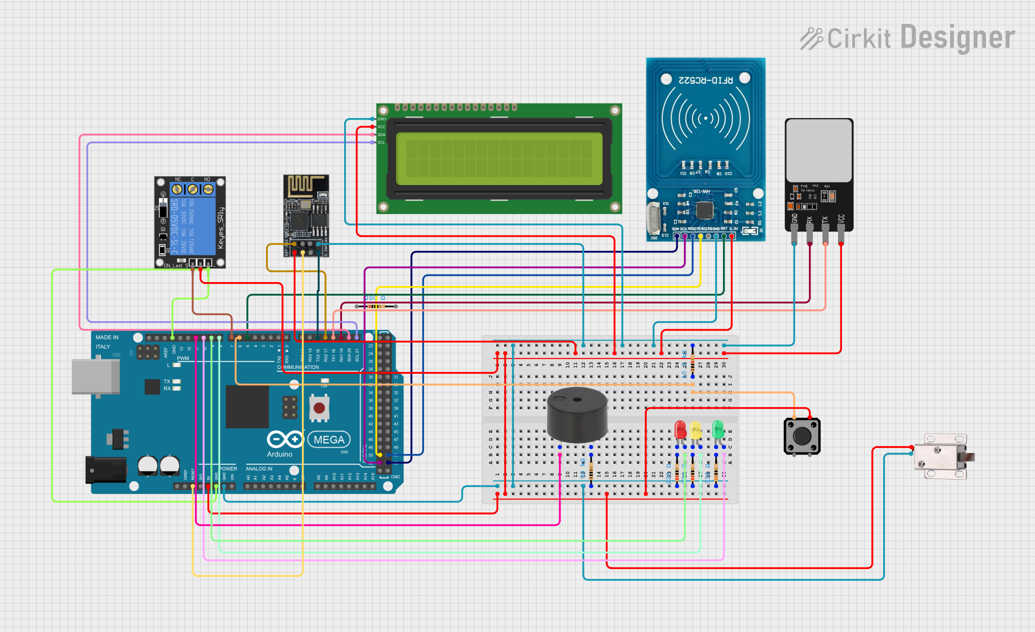
Circuit Documentation
Summary
This circuit is designed to control access using an RFID reader, a fingerprint scanner, and a WiFi module for remote logging. The system uses an Arduino Mega 2560 as the main microcontroller. It includes various components such as LEDs, a buzzer, a relay, a solenoid lock, and an LCD display to provide user feedback and control mechanisms.
Component List
Arduino Mega 2560
- Description: Main microcontroller used to control the entire system.
- Pins: IOREF, RESET, 3V3, 5V, GND, VIN, A0-A15, D0-D53, AREF, SDA, SCL
RFID-RC522
- Description: RFID reader used to read RFID cards.
- Pins: VCC (3.3V), RST, GND, IRQ, MISO, MOSI, SCK, SDA
Fingerprint Scanner
- Description: Used to scan and verify fingerprints.
- Pins: VCC, TX, RX, GND
WiFi module ESP8266-01
- Description: WiFi module used for remote logging and communication.
- Pins: RX, GPIO0, GPIO2, GND, +3V3, Reset, CH-PD Chip power down, TX
LED: Two Pin (green)
- Description: Green LED used for visual feedback.
- Pins: cathode, anode
Buzzer
- Description: Buzzer used for audio feedback.
- Pins: PIN, GND
LED: Two Pin (yellow)
- Description: Yellow LED used for visual feedback.
- Pins: cathode, anode
1-Channel Relay (5V 10A)
- Description: Relay used to control the solenoid lock.
- Pins: NC, signal, C, power, NO, ground
Tactile Switch Buttons - 12mm Square
- Description: Push button used for manual control.
- Pins: 3, 1, 4, 2
12V Solenoid Lock
- Description: Solenoid lock used to lock/unlock the door.
- Pins: VCC, GND
Resistor (200 Ohms)
- Description: Resistor used in the circuit.
- Pins: pin1, pin2
LED: Two Pin (red)
- Description: Red LED used for visual feedback.
- Pins: cathode, anode
16x2 I2C LCD
- Description: LCD display used to provide visual feedback.
- Pins: GND, VCC, SDA, SCL
Resistor (220 Ohms)
- Description: Resistor used in the circuit.
- Pins: pin1, pin2
Resistor (330 Ohms)
- Description: Resistor used in the circuit.
- Pins: pin1, pin2
Resistor (1000 Ohms)
- Description: Resistor used in the circuit.
- Pins: pin1, pin2
Resistor (10000 Ohms)
- Description: Resistor used in the circuit.
- Pins: pin1, pin2
Wiring Details
Arduino Mega 2560
- 5V: Connected to VCC of 12V solenoid lock, power pin of 1-Channel Relay, +3V3 of WiFi module ESP8266-01, VCC of 16x2 I2C LCD, VCC (3.3V) of RFID-RC522, VCC of Fingerprint Scanner
- GND: Connected to pin1 of multiple resistors, GND of 12V solenoid lock, GND of WiFi module ESP8266-01, GND of 16x2 I2C LCD, GND of RFID-RC522, GND of Fingerprint Scanner, ground of 1-Channel Relay
- RESET: Connected to Reset of WiFi module ESP8266-01
- D5 PWM: Connected to RST of RFID-RC522
- D6 PWM: Connected to pin1 of 10000 Ohms resistor, pin1 of Tactile Switch Buttons
- D7 PWM: Connected to signal of 1-Channel Relay
- D8 PWM: Connected to anode of yellow LED
- D9 PWM: Connected to anode of red LED
- D10 PWM: Connected to anode of green LED
- D11 PWM: Connected to PIN of buzzer
- D16 PWM/TX2: Connected to TX of WiFi module ESP8266-01
- D17 PWM/RX2: Connected to RX of WiFi module ESP8266-01
- D18/TX1: Connected to TX of Fingerprint Scanner
- D19/RX1: Connected to RX of Fingerprint Scanner
- D20/SDA: Connected to SDA of 16x2 I2C LCD
- D21/SCL: Connected to SCL of 16x2 I2C LCD
- D50: Connected to MISO of RFID-RC522
- D51: Connected to MOSI of RFID-RC522
- D52: Connected to SCK of RFID-RC522
- D53: Connected to SDA of RFID-RC522
RFID-RC522
- VCC (3.3V): Connected to 5V of Arduino Mega 2560
- RST: Connected to D5 PWM of Arduino Mega 2560
- GND: Connected to GND of Arduino Mega 2560
- MISO: Connected to D50 of Arduino Mega 2560
- MOSI: Connected to D51 of Arduino Mega 2560
- SCK: Connected to D52 of Arduino Mega 2560
- SDA: Connected to D53 of Arduino Mega 2560
Fingerprint Scanner
- VCC: Connected to 5V of Arduino Mega 2560
- TX: Connected to D18/TX1 of Arduino Mega 2560
- RX: Connected to D19/RX1 of Arduino Mega 2560
- GND: Connected to GND of Arduino Mega 2560
WiFi module ESP8266-01
- RX: Connected to D17 PWM/RX2 of Arduino Mega 2560
- TX: Connected to D16 PWM/TX2 of Arduino Mega 2560
- GND: Connected to GND of Arduino Mega 2560
- +3V3: Connected to 5V of Arduino Mega 2560
- Reset: Connected to RESET of Arduino Mega 2560
LED: Two Pin (green)
- anode: Connected to D10 PWM of Arduino Mega 2560
- cathode: Connected to pin2 of 330 Ohms resistor
Buzzer
- PIN: Connected to D11 PWM of Arduino Mega 2560
- GND: Connected to pin2 of 1000 Ohms resistor
LED: Two Pin (yellow)
- anode: Connected to D8 PWM of Arduino Mega 2560
- cathode: Connected to pin2 of 220 Ohms resistor
1-Channel Relay (5V 10A)
- signal: Connected to D7 PWM of Arduino Mega 2560
- power: Connected to 5V of Arduino Mega 2560
- ground: Connected to GND of Arduino Mega 2560
Tactile Switch Buttons - 12mm Square
- 1: Connected to pin1 of 10000 Ohms resistor
- 2: Connected to 5V of Arduino Mega 2560
12V Solenoid Lock
- VCC: Connected to 5V of Arduino Mega 2560
- GND: Connected to GND of Arduino Mega 2560
Resistor (200 Ohms)
- pin1: Connected to GND of Arduino Mega 2560
LED: Two Pin (red)
- anode: Connected to D9 PWM of Arduino Mega 2560
- cathode: Connected to pin2 of 220 Ohms resistor
16x2 I2C LCD
- VCC: Connected to 5V of Arduino Mega 2560
- GND: Connected to GND of Arduino Mega 2560
- SDA: Connected to D20/SDA of Arduino Mega 2560
- SCL: Connected to D21/SCL of Arduino Mega 2560
Resistor (220 Ohms)
- pin1: