
ESP32-S3 Beehive Monitoring and Control System with DHT22, BH1750, and MPU6050
View and Edit Project In Cirkit Designer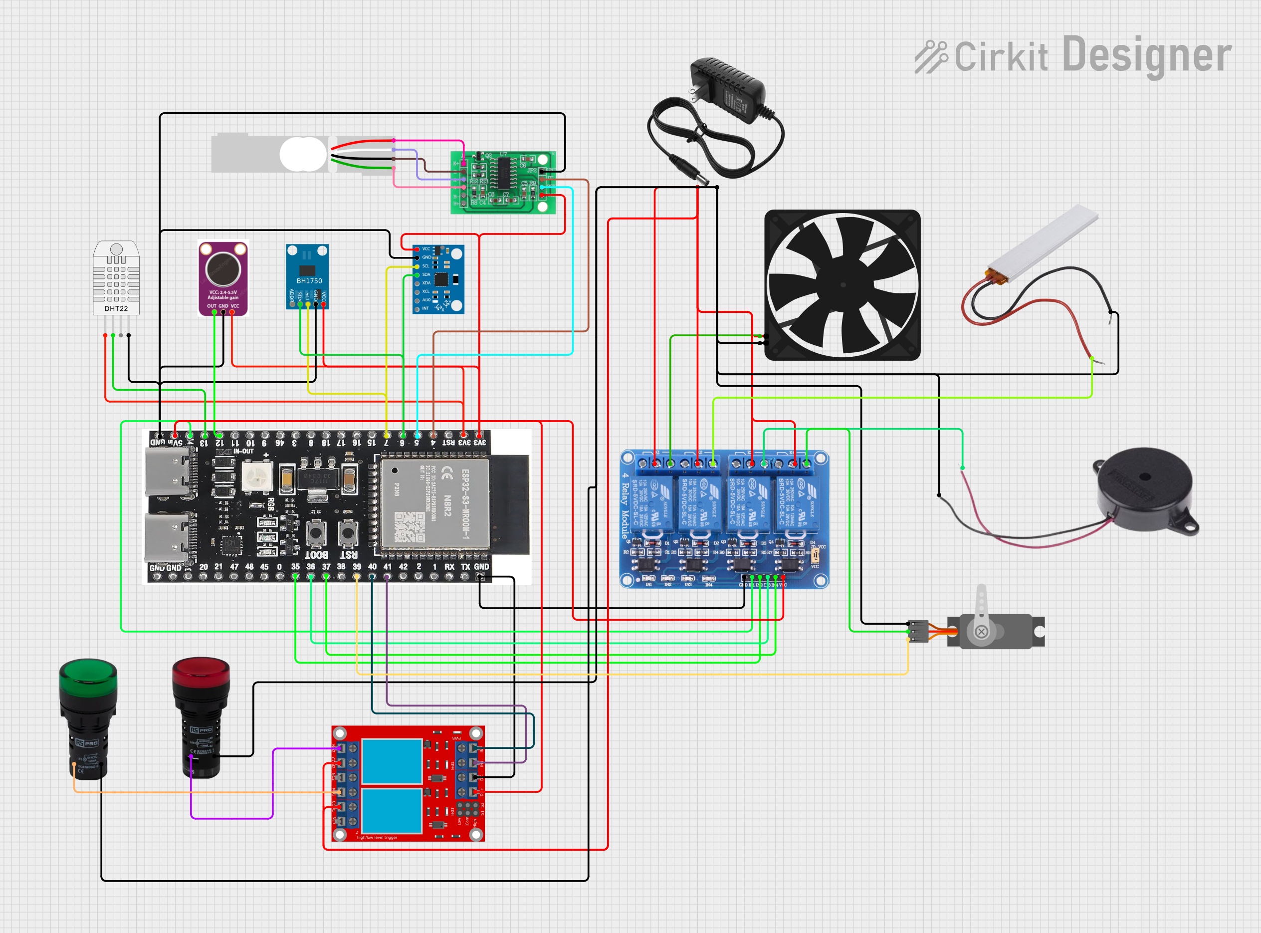
Beehive Monitoring and Control System
Summary
This document provides a detailed overview of a Beehive Monitoring and Control System. The system monitors temperature, humidity, weight, sound, and acceleration within a beehive using various sensors. It also controls a fan, heater, buzzer, indicator lamps, and a servo motor via relays. The system is built around an ESP32-S3 microcontroller, which interfaces with multiple sensors and actuators.
Component List
DHT22 (Wokwi Compatible)
- Description: Digital temperature and humidity sensor.
- Pins: VCC, SDA, NC, GND
MAX4466
- Description: Microphone amplifier module.
- Pins: OUT, GND, VCC
Load Cell - Red/white/black/green
- Description: Weight sensor.
- Pins: E+, A-, E-, A+
BH1750
- Description: Light intensity sensor.
- Pins: VCC, GND, SCL, SDA, ADDR
MPU6050
- Description: Accelerometer and gyroscope sensor.
- Pins: vcc, gnd, scl, sda, xda, xcl, AD0, int, 3.3v
Relay 4 Channel 5v
- Description: 4-channel relay module for controlling high-power devices.
- Pins: GND, IN1, IN2, IN3, IN4, VCC, COM1, COM2, COM3, COM4, NO1, NO2, NO3, NO4, NC1, NC2, NC3, NC4
PTC
- Description: Positive temperature coefficient thermistor.
- Pins: Neutral, Live
Servo (Wokwi Compatible)
- Description: Servo motor.
- Pins: GND, V+, PWM
ESP32-S3-DevKitC-1-N8R2
- Description: Microcontroller development board.
- Pins: GND, 5Vin, 14, 13, 12, 11, 10, 9, 46, 3, 8, 18, 17, 16, 15, 7, 6, 5, 4, 3v3, TX, RX, 1, 2, 42, 41, 40, 39, 38, 37, 36, 35, 0, 45, 48, 47, 21, 20, 19
Fan
- Description: Cooling fan.
- Pins: GND, 5V
12v power supply
- Description: Power supply unit.
- Pins: +, -
HX711 - Bridge Sensor Interface
- Description: Load cell amplifier.
- Pins: E+, E-, A-, A+, B-, B+, GND - GROUND, DATA (OUT), SCK - CLOCK (IN), 3.3/3.5V Supply
Buzzer
- Description: Audio signaling device.
- Pins: POSITIVE, NEGATIVE
2 channel relay module
- Description: 2-channel relay module for controlling high-power devices.
- Pins: N.O. 2, COM 2, N.C. 2, N.O. 1, COM 1, N.C. 1, pin 7, pin 8, pin 9, pin 10, pin 11, pin 12, VCC+, VCC- (GND), IN 1, IN 2
Pilot Lamp Green
- Description: Indicator lamp.
- Pins: X1, X2
Pilot Lamp Red
- Description: Indicator lamp.
- Pins: X1, X2
Wiring Details
DHT22 (Wokwi Compatible)
- VCC: Connected to ESP32-S3 3v3
- SDA: Connected to ESP32-S3 pin 13
- GND: Connected to ESP32-S3 GND
MAX4466
- OUT: Connected to ESP32-S3 pin 12
- VCC: Connected to ESP32-S3 3v3
- GND: Connected to ESP32-S3 GND
Load Cell - Red/white/black/green
- E+: Connected to HX711 E+
- A-: Connected to HX711 A-
- E-: Connected to HX711 E-
- A+: Connected to HX711 A+
BH1750
- VCC: Connected to ESP32-S3 3v3
- GND: Connected to ESP32-S3 GND
- SCL: Connected to ESP32-S3 pin 7
- SDA: Connected to ESP32-S3 pin 6
MPU6050
- vcc: Connected to ESP32-S3 3v3
- gnd: Connected to ESP32-S3 GND
- scl: Connected to ESP32-S3 pin 7
- sda: Connected to ESP32-S3 pin 6
Relay 4 Channel 5v
- VCC: Connected to ESP32-S3 5Vin
- GND: Connected to ESP32-S3 GND
- IN1: Connected to ESP32-S3 pin 14
- IN2: Connected to ESP32-S3 pin 35
- IN3: Connected to ESP32-S3 pin 36
- IN4: Connected to ESP32-S3 pin 37
- NO1: Connected to Fan 5V
- NO2: Connected to PTC Live
- NO3: Connected to Buzzer POSITIVE
- NO4: Connected to Servo V+
- COM1, COM2, COM3, COM4: Connected to 12v power supply +
PTC
- Neutral: Connected to 12v power supply -
- Live: Connected to Relay 4 Channel 5v NO2
Servo (Wokwi Compatible)
- GND: Connected to 12v power supply -
- V+: Connected to Relay 4 Channel 5v NO4
- PWM: Connected to ESP32-S3 pin 39
ESP32-S3-DevKitC-1-N8R2
- GND: Connected to common ground
- 5Vin: Connected to 5V power supply
- 3v3: Connected to 3.3V power supply
- Pin 14: Connected to Relay 4 Channel 5v IN1
- Pin 13: Connected to DHT22 SDA
- Pin 12: Connected to MAX4466 OUT
- Pin 7: Connected to BH1750 SCL and MPU6050 scl
- Pin 6: Connected to BH1750 SDA and MPU6050 sda
- Pin 5: Connected to HX711 SCK - CLOCK (IN)
- Pin 4: Connected to HX711 DATA (OUT)
- Pin 41: Connected to 2 channel relay module IN 1
- Pin 40: Connected to 2 channel relay module IN 2
- Pin 39: Connected to Servo PWM
- Pin 37: Connected to Relay 4 Channel 5v IN4
- Pin 36: Connected to Relay 4 Channel 5v IN3
- Pin 35: Connected to Relay 4 Channel 5v IN2
Fan
- GND: Connected to 12v power supply -
- 5V: Connected to Relay 4 Channel 5v NO1
12v power supply
- +: Connected to Relay 4 Channel 5v COM1, COM2, COM3, COM4 and 2 channel relay module COM 1, COM 2
- -: Connected to common ground
HX711 - Bridge Sensor Interface
- E+: Connected to Load Cell E+
- E-: Connected to Load Cell E-
- A-: Connected to Load Cell A-
- A+: Connected to Load Cell A+
- GND - GROUND: Connected to ESP32-S3 GND
- DATA (OUT): Connected to ESP32-S3 pin 4
- SCK - CLOCK (IN): Connected to ESP32-S3 pin 5
- 3.3/3.5V Supply: Connected to ESP32-S3 3v3
Buzzer
- POSITIVE: Connected to Relay 4 Channel 5v NO3
- NEGATIVE: Connected to 12v power supply -
2 channel relay module
- VCC+: Connected to ESP32-S3 5Vin
- VCC- (GND): Connected to ESP32-S3 GND
- IN 1: Connected to ESP32-S3 pin 41
- IN 2: Connected to ESP32-S3 pin 40
- N.O. 1: Connected to Pilot Lamp Green X1
- N.O. 2: Connected to Pilot Lamp Red X1
- COM 1: Connected to 12v power supply +
- COM 2: