
Transistor-Based LED Driver Circuit with Capacitive Filtering
View and Edit Project In Cirkit Designer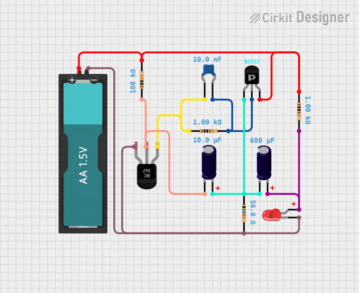
Circuit Documentation
Summary of the Circuit
This circuit appears to be a simple electronic system that includes a combination of active and passive components. The active components include PNP and NPN transistors, which are likely used for switching or amplification purposes. The passive components include resistors, capacitors, and an LED. The circuit is powered by a single AA 1.5V battery. The resistors are of various values, suggesting they are used for biasing the transistors, limiting current, or setting time constants with capacitors. The capacitors are of different types and values, indicating they may be used for filtering, timing, or storing charge. The LED indicates output or status. Without a microcontroller or additional context, the exact function of the circuit is not clear, but it could be a simple light indicator or a part of a larger system.
Component List
Active Components
PNP Transistor (CBE)
- A PNP transistor with Collector, Base, and Emitter pins.
BC547 Transistor
- An NPN transistor, commonly used for amplification and switching.
Passive Components
Resistors
- Multiple resistors with different resistance values (56 Ohms, 1 kOhms, 100 kOhms).
LED: Two Pin (red)
- A red light-emitting diode with anode and cathode pins.
Ceramic Capacitor
- A capacitor with a capacitance of 10 nF.
Electrolytic Capacitors
- Two electrolytic capacitors with capacitances of 10 µF and 680 nF.
Battery AA 1.5V
- A single-cell AA battery providing a voltage of 1.5V.
Other
- Comments
- Placeholder components that may represent annotations or notes in the circuit design.
Wiring Details
PNP Transistor (CBE)
- Collector connected to:
- 56 Ohm resistor
- 10 µF electrolytic capacitor
- 680 nF electrolytic capacitor
- Base connected to:
- 1 kOhm resistor
- 10 nF ceramic capacitor
- Emitter connected to:
- 100 kOhm resistor
- Battery VCC
BC547 Transistor
- Collector connected to:
- 1 kOhm resistor
- 10 nF ceramic capacitor
- Base connected to:
- 100 kOhm resistor
- 10 µF electrolytic capacitor
- Emitter connected to:
- Battery GND
- 56 Ohm resistor
- Red LED cathode
Resistors
- 56 Ohm resistor connected between:
- BC547 Transistor Emitter
- Red LED cathode
- Battery GND
- 1 kOhm resistors connected between:
- PNP Transistor Base and Ceramic Capacitor
- BC547 Transistor Collector and Ceramic Capacitor
- 100 kOhm resistor connected between:
- Battery VCC
- PNP Transistor Emitter
- BC547 Transistor Base
LED: Two Pin (red)
- Anode connected to:
- 1 kOhm resistor
- 680 nF electrolytic capacitor
- Cathode connected to:
- Battery GND
- 56 Ohm resistor
- BC547 Transistor Emitter
Ceramic Capacitor
- One side connected to:
- PNP Transistor Base
- 1 kOhm resistor
- Other side connected to:
- BC547 Transistor Collector
- 1 kOhm resistor
Electrolytic Capacitors
- 10 µF capacitor connected between:
- PNP Transistor Collector
- BC547 Transistor Base
- 680 nF capacitor connected between:
- PNP Transistor Collector
- Red LED anode
Battery AA 1.5V
- VCC connected to:
- PNP Transistor Emitter
- 100 kOhm resistor
- GND connected to:
- BC547 Transistor Emitter
- 56 Ohm resistor
- Red LED cathode
Documented Code
No code has been provided for this circuit. If there were any microcontrollers or programmable devices included, the code for those devices would be documented in this section.