
Arduino UNO Controlled Robotic Vehicle with Ultrasonic Obstacle Detection and Joystick Operation
View and Edit Project In Cirkit Designer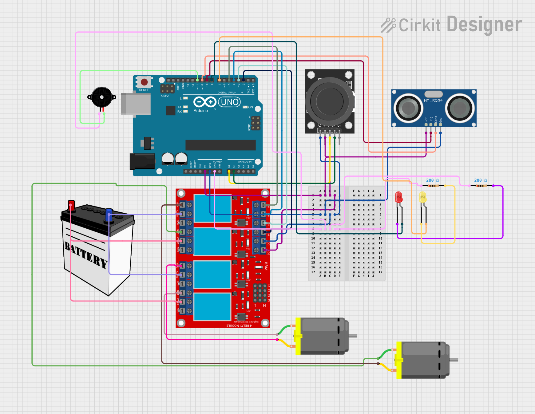
Circuit Documentation
Summary
This circuit is designed to interface an Arduino UNO with a variety of components including a KY-023 Dual Axis Joystick Module, an HC-SR04 Ultrasonic Sensor, a 4-channel relay module, two DC Motors, two LEDs (red and yellow), a Piezo Speaker, and two resistors. The circuit is powered by a 12V Battery and the Arduino UNO's 5V output. The primary functions of this circuit include distance measurement, motor control via joystick input, visual indicators through LEDs, and audio feedback using a Piezo Speaker.
Component List
Arduino UNO
A microcontroller board based on the ATmega328P. It has 14 digital input/output pins, 6 analog inputs, a USB connection, a power jack, an ICSP header, and a reset button.
12V Battery
Provides the power source for the relay module and the DC Motors.
KY-023 Dual Axis Joystick Module
A joystick controller that provides two analog outputs corresponding to the X and Y axes and a digital output for the joystick switch.
HC-SR04 Ultrasonic Sensor
An ultrasonic distance sensor that can measure distances from 2cm to 400cm with an accuracy of 3mm.
4-channel Relay Module
Allows for control of high-power devices using low-power signals from the Arduino. It has four relays that can be individually controlled.
DC Motor (x2)
Electric motors that convert electrical energy into mechanical energy.
LED: Two Pin (red)
A red light-emitting diode that emits red light when a forward current passes through it.
LED: Two Pin (yellow)
A yellow light-emitting diode that emits yellow light when a forward current passes through it.
Piezo Speaker
An electronic device that can generate sound when an electrical signal is applied to it.
Resistor (200 Ohms) (x2)
A passive two-terminal electrical component that implements electrical resistance as a circuit element.
Wiring Details
Arduino UNO
- 5V and GND pins are used to power the HC-SR04 Ultrasonic Sensor, KY-023 Joystick Module, and the 4-channel relay module.
- Analog pins A0 and A1 are connected to the VRx and VRy outputs of the KY-023 Joystick Module for X and Y-axis readings.
- Digital pins D2 to D5 are connected to the IN 1 to IN 4 inputs of the 4-channel relay module to control the relays.
- Digital pin D8 is connected to the anode of the red LED through a 200 Ohm resistor.
- Digital pin D7 is connected to the anode of the yellow LED through a 200 Ohm resistor.
- Digital pin D11 is connected to the Piezo Speaker.
- Digital pins D9 and D10 are connected to the TRIG and ECHO pins of the HC-SR04 Ultrasonic Sensor.
12V Battery
- VCC is connected to the COM 1 and COM 3 of the 4-channel relay module.
- GND is connected to the COM 4 and COM 2 of the 4-channel relay module.
KY-023 Dual Axis Joystick Module
- +5V and GND are powered by the Arduino UNO.
- VRx and VRy are connected to the A0 and A1 analog inputs of the Arduino UNO.
HC-SR04 Ultrasonic Sensor
- VCC and GND are powered by the Arduino UNO.
- TRIG and ECHO are connected to the D9 and D10 digital pins of the Arduino UNO.
4-channel Relay Module
- VCC+ and VCC- (GND) are powered by the Arduino UNO.
- IN 1 to IN 4 are controlled by the D2 to D5 digital pins of the Arduino UNO.
- N.O. 1 to N.O. 4 are connected to the DC Motors.
DC Motors
- One terminal of each motor is connected to the N.O. terminals of the 4-channel relay module.
- The other terminal of each motor is connected to the 12V Battery.
LEDs (Red and Yellow)
- The anode of each LED is connected to the D8 and D7 digital pins of the Arduino UNO through a 200 Ohm resistor.
- The cathode of each LED is connected to GND.
Piezo Speaker
- One terminal is connected to the D11 digital pin of the Arduino UNO.
- The other terminal is connected to GND through a 200 Ohm resistor.
Resistor (200 Ohms)
- One resistor is connected between the red LED and the Arduino UNO.
- One resistor is connected between the yellow LED and the Arduino UNO.
Documented Code
// Define pin connections
const int trigPin = 9;
const int echoPin = 10;
const int joystickXPin = A0;
const int joystickYPin = A1;
const int relay1Pin = 2;
const int relay2Pin = 3;
const int relay3Pin = 4;
const int relay4Pin = 5;
const int redLEDPin = 8;
const int yellowLEDPin = 7;
const int piezoPin = 11;

// Variables for ultrasonic sensor
long duration;
int distance;

void setup() {
  // Initialize pins
  pinMode(trigPin, OUTPUT);
  pinMode(echoPin, INPUT);
  pinMode(relay1Pin, OUTPUT);
  pinMode(relay2Pin, OUTPUT);
  pinMode(relay3Pin, OUTPUT);
  pinMode(relay4Pin, OUTPUT);
  pinMode(redLEDPin, OUTPUT);
  pinMode(yellowLEDPin, OUTPUT);
  pinMode(piezoPin, OUTPUT);

  // Initialize relay to be off
  digitalWrite(relay1Pin, HIGH);
  digitalWrite(relay2Pin, HIGH);
  digitalWrite(relay3Pin, HIGH);
  digitalWrite(relay4Pin, HIGH);
}

void loop() {
  // Read distance from ultrasonic sensor
  digitalWrite(trigPin, LOW);
  delayMicroseconds(2);
  digitalWrite(trigPin, HIGH);
  delayMicroseconds(10);
  digitalWrite(trigPin, LOW);
  duration = pulseIn(echoPin, HIGH);
  distance = duration * 0.034 / 2;

  // Read joystick position
  int joystickX = analogRead(joystickXPin);
  int joystickY = analogRead(joystickYPin);

  // Control motors via relay based on joystick position
  if (joystickX > 512) { // Assuming center position is 512
    digitalWrite(relay1Pin, LOW); // Turn on motor 1
  } else {
    digitalWrite(relay1Pin, HIGH); // Turn off motor 1
  }

  if (joystickY > 512) {
    digitalWrite(relay3Pin, LOW); // Turn on motor 2
  } else {
    digitalWrite(relay3Pin, HIGH); // Turn off motor 2
  }

  // Control LEDs based on distance
  if (distance < 10) {
    digitalWrite(redLEDPin, HIGH);
    digitalWrite(yellowLEDPin, LOW);
  } else if (distance < 20) {
    digitalWrite(redLEDPin, LOW);
    digitalWrite(yellowLEDPin, HIGH);
  } else {
    digitalWrite(redLEDPin, LOW);
    digitalWrite(yellowLEDPin, LOW);
  }

  // Play a sound if an object is very close
  if (distance < 5) {
    tone(piezoPin, 1000); // Play 1kHz tone
    delay(100); // for 100ms
    noTone(piezoPin);
  }

  // Add a short delay before the next loop iteration
  delay(100);
}
This code is designed to run on the Arduino UNO and controls the various components based on sensor inputs and provides feedback through LEDs and a Piezo Speaker.