
Arduino Mega 2560 Controlled Multi-Servo Random Positioning System
View and Edit Project In Cirkit Designer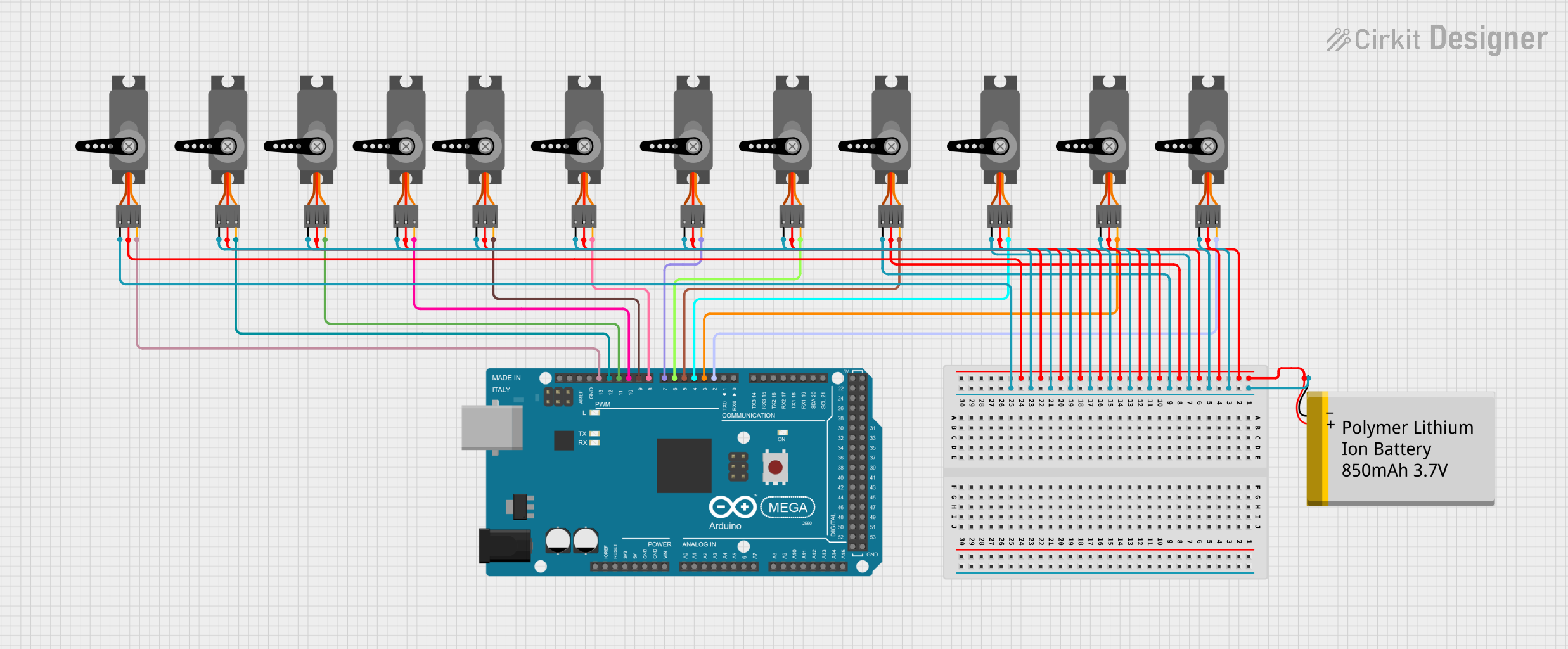
Circuit Documentation
Summary
This circuit is designed to control multiple servo motors using an Arduino Mega 2560 microcontroller. The servos are powered by a Polymer Lithium Ion Battery with a capacity of 850mAh. The Arduino Mega 2560 provides Pulse Width Modulation (PWM) signals to control the position of each servo motor. The circuit is intended for applications where precise angular control of multiple servos is required, such as in robotics or automated systems.
Component List
Servo Motors
- Component Name: Servo
- Description: A servo motor is an actuator that allows for precise control of angular position. It typically consists of a motor coupled to a sensor for position feedback.
- Pins: GND, VCC, PWM
Polymer Lithium Ion Battery - 850mAh
- Component Name: Polymer Lithium Ion Battery - 850mAh
- Description: A rechargeable battery that provides power to the circuit. It has a capacity of 850mAh, suitable for powering small electronics like servo motors.
- Pins: GND, VCC
Arduino Mega 2560
- Component Name: Arduino Mega 2560
- Description: A microcontroller board based on the ATmega2560. It has 54 digital input/output pins (of which 15 can be used as PWM outputs), 16 analog inputs, 4 UARTs (hardware serial ports), a 16 MHz crystal oscillator, a USB connection, a power jack, an ICSP header, and a reset button.
- Pins: Multiple digital and analog pins, including dedicated PWM pins.
Wiring Details
Servo Motors
Each servo motor has the following connections:
- GND: Connected to the ground (GND) of the battery.
- VCC: Connected to the positive terminal (VCC) of the battery.
- PWM: Connected to a dedicated PWM pin on the Arduino Mega 2560.
Polymer Lithium Ion Battery - 850mAh
- GND: Connected to the ground (GND) pins of all servo motors and the Arduino Mega 2560.
- VCC: Connected to the VCC pins of all servo motors.
Arduino Mega 2560
- PWM Pins (D2, D3, D4, D5, D6, D7, D8, D9, D10, D11, D12, D13): Each pin is connected to the PWM pin of a different servo motor.
Documented Code
#include <Servo.h>

// Define the number of servos
const int numServos = 12;
Servo servos[numServos];

// Define the pins for the servos
int servoPins[numServos] = {2, 3, 4, 5, 6, 7, 8, 9, 10, 11, 12, 13};

void setup() {
  // Attach the servos to their respective pins
  for (int i = 0; i < numServos; i++) {
    servos[i].attach(servoPins[i]);
  }
}

void loop() {
  // Rotate each servo to a random position
  for (int i = 0; i < numServos; i++) {
    int randomPosition = random(0, 181);  // Generate a random position between 0 and 180 degrees
    servos[i].write(randomPosition);
  }

  // Wait for a random amount of time between 500ms and 2000ms
  int randomDelay = random(500, 2000);
  delay(randomDelay);
}
The code provided is an Arduino sketch that initializes 12 servo objects and attaches them to PWM pins D2 to D13 on the Arduino Mega 2560. In the loop function, each servo is moved to a random position between 0 and 180 degrees, and then the system pauses for a random delay between 500ms and 2000ms before moving the servos again. This code is intended to demonstrate the basic functionality of servo control with an Arduino.