
Arduino UNO Based GSM and GPS Tracking System with IR Sensor and Motor Control
View and Edit Project In Cirkit Designer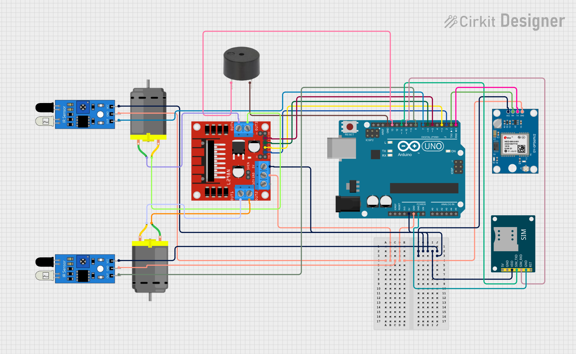
Circuit Documentation
Summary
This circuit integrates various components to perform a set of functions that likely involve communication, positioning, motor control, and sensing. An Arduino UNO serves as the central microcontroller, interfacing with a SIM800L GSM module for cellular communication, a Neo 6M GPS module for location tracking, an L298N DC motor driver for controlling two DC motors, and two IR sensors for object detection or proximity sensing. Additionally, a buzzer is included for audible feedback. The circuit is powered through the Arduino UNO's 5V pin, which supplies power to the other components.
Component List
Arduino UNO
- Microcontroller board based on the ATmega328P
- Provides digital and analog I/O pins
- Includes power supply pins and communication interfaces
SIM800L GSM Module
- Cellular communication module
- Capable of sending SMS and making voice calls
- Requires a power supply and serial communication with the microcontroller
Neo 6M GPS Module
- GPS receiver module for positioning
- Communicates with the microcontroller via serial interface
L298N DC Motor Driver
- Dual H-bridge motor driver
- Capable of driving two DC motors
- Requires a power supply and control signals from the microcontroller
IR Sensor (2x)
- Infrared proximity sensor
- Outputs a digital signal when an object is detected
- Requires a power supply and a digital input pin on the microcontroller
DC Motor (2x)
- Electric motor powered by DC voltage
- Controlled by the motor driver
Buzzer
- Audible signaling device
- Activated by a digital signal from the microcontroller
Wiring Details
Arduino UNO
5Vpin connected to the power supply pins of the SIM800L GSM Module, both IR sensors, the Neo 6M GPS Module, and the L298N DC motor driverGNDpin connected to the ground pins of all components- Digital pins
D0andD1connected to theTXandRXpins of the Neo 6M GPS Module for serial communication - Digital pins
D2andD3connected to theIN1andIN2pins of the L298N DC motor driver for motor control - Digital pins
D5andD6connected to theIN3andIN4pins of the L298N DC motor driver for motor control - Digital pin
D7connected to theoutpin of one IR sensor - Digital pin
D8connected to theoutpin of the other IR sensor - Digital pin
D10connected to theSIM_RXDpin of the SIM800L GSM Module for serial communication - Digital pin
D11connected to theSIM_TXDpin of the SIM800L GSM Module for serial communication - Digital pin
D13connected to thePINpin of the buzzer for control
SIM800L GSM Module
VDDpin connected to the5Vpin of the Arduino UNOGNDpin connected to theGNDpin of the Arduino UNOSIM_TXDpin connected to theD11pin of the Arduino UNOSIM_RXDpin connected to theD10pin of the Arduino UNO
Neo 6M GPS Module
VCCpin connected to the5Vpin of the Arduino UNOGNDpin connected to theGNDpin of the Arduino UNOTXpin connected to theD0pin of the Arduino UNORXpin connected to theD1pin of the Arduino UNO
L298N DC Motor Driver
5Vpin connected to the5Vpin of the Arduino UNOGNDpin connected to theGNDpin of the Arduino UNOIN1toIN4pins connected to theD2,D3,D5, andD6pins of the Arduino UNO for motor controlOUT1toOUT4pins connected to the respective pins of the two DC Motors
IR Sensors
vccpins connected to the5Vpin of the Arduino UNOgndpins connected to theGNDpin of the Arduino UNOoutpins connected to theD7andD8pins of the Arduino UNO
DC Motors
pin 1andpin 2of each motor connected to theOUT1toOUT4pins of the L298N DC motor driver
Buzzer
PINpin connected to theD13pin of the Arduino UNOGNDpin connected to theGNDpin of the Arduino UNO
Documented Code
Arduino UNO Code (sketch.ino)
void setup() {
  // put your setup code here, to run once:

}

void loop() {
  // put your main code here, to run repeatedly:

}
Note: The provided code is a template and does not include specific functionality. It needs to be populated with the logic to control the components as per the circuit's requirements.