
Circuit Documentation
Summary of the Circuit
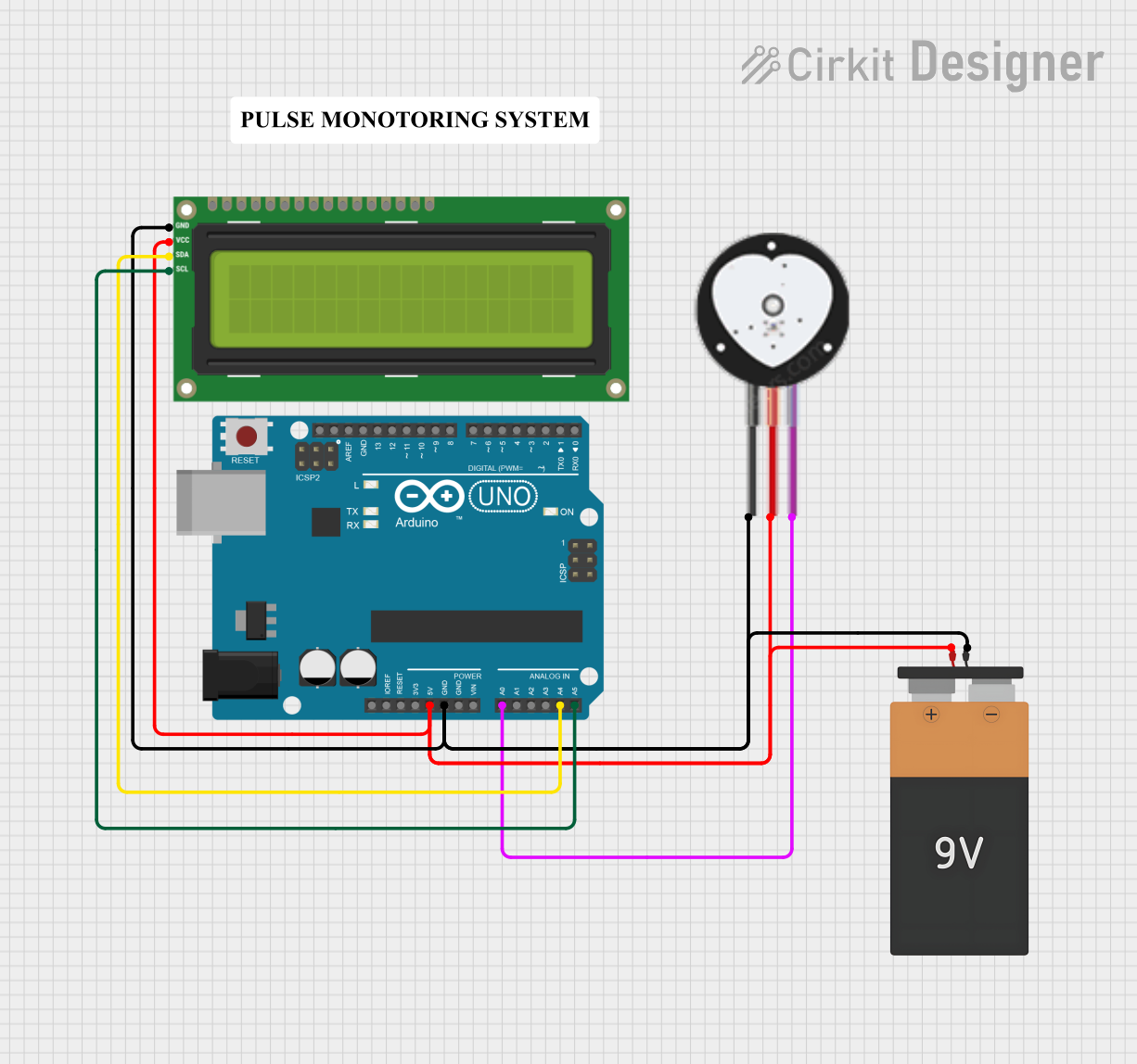
The circuit in question is designed to monitor the heart pulse rate and display the beats per minute (BPM) on an I2C LCD 16x2 screen. It consists of an Arduino UNO microcontroller, a heart pulse sensor, an I2C LCD 16x2 screen, and a 9V battery to power the system. The Arduino UNO reads the pulse signal from the heart pulse sensor, processes the signal, and then displays the calculated BPM on the LCD screen. The communication between the Arduino and the LCD screen is facilitated through the I2C protocol.
Component List
Arduino UNO
- Description: A microcontroller board based on the ATmega328P.
- Purpose: Acts as the central processing unit of the circuit, reading sensor data, processing it, and controlling the LCD display.
Heart Pulse Sensor
- Description: A sensor that detects heart rate.
- Purpose: Measures the pulse rate of a human heart and sends the data to the Arduino UNO.
I2C LCD 16x2 Screen
- Description: A 16x2 character LCD display that uses the I2C communication protocol.
- Purpose: Displays the pulse rate measured by the heart pulse sensor.
Battery 9V
- Description: A standard 9V battery.
- Purpose: Provides power to the circuit components.
Wiring Details
Arduino UNO
- 5V: Connected to the VCC of the Heart Pulse Sensor, I2C LCD 16x2 Screen, and the positive terminal of the Battery 9V.
- GND: Connected to the GND of the Heart Pulse Sensor, I2C LCD 16x2 Screen, and the negative terminal of the Battery 9V.
- A0: Receives the SIGNAL from the Heart Pulse Sensor.
- A4 (SDA): Connected to the SDA pin of the I2C LCD 16x2 Screen for I2C data.
- A5 (SCL): Connected to the SCL pin of the I2C LCD 16x2 Screen for I2C clock.
Heart Pulse Sensor
- VCC: Connected to the 5V output from the Arduino UNO.
- GND: Connected to the ground (GND) on the Arduino UNO.
- SIGNAL: Connected to the A0 pin on the Arduino UNO.
I2C LCD 16x2 Screen
- VCC (5V): Connected to the 5V output from the Arduino UNO.
- GND: Connected to the ground (GND) on the Arduino UNO.
- SDA: Connected to the A4 pin on the Arduino UNO for I2C data.
- SCL: Connected to the A5 pin on the Arduino UNO for I2C clock.
Battery 9V
- VCC: Connected to the 5V input on the Arduino UNO.
- GND: Connected to the ground (GND) on the Arduino UNO.
Documented Code
#include <Wire.h>
#include <LiquidCrystal_I2C.h>

// Initialize the LCD (address 0x27, 16 columns and 2 rows)
LiquidCrystal_I2C lcd(0x27, 16, 2);

// Pulse sensor pin
const int pulsePin = A0;
int pulseValue;
int bpm; // Beats per minute

void setup() {
  Serial.begin(9600);
  lcd.begin();
  lcd.backlight();
  lcd.print("Pulse Rate Monitor");
  delay(2000); // Display title for 2 seconds
  lcd.clear();
}

void loop() {
  pulseValue = analogRead(pulsePin);

  // Simple processing to convert pulseValue to BPM
  bpm = map(pulseValue, 0, 1023, 0, 200); // Adjust mapping as needed

  // Display on LCD
  lcd.setCursor(0, 0);
  lcd.print("Pulse Rate: ");
  lcd.print(bpm);
  lcd.print(" bpm");

  // Debugging output to Serial Monitor
  Serial.print("Pulse Value: ");
  Serial.print(pulseValue);
  Serial.print(" | BPM: ");
  Serial.println(bpm);

  delay(1000); // Update every second
}
Filename: sketch.ino
Description: This code initializes the I2C LCD screen and reads the analog pulse signal from the heart pulse sensor connected to pin A0. It maps the analog value to a BPM value and displays it on the LCD. Additionally, it outputs the raw pulse value and calculated BPM to the Serial Monitor for debugging purposes. The display is updated every second.