Arduino Mega 2560 Controlled Quadcopter with GPS, Compass, Ultrasonic Sensors, and LoRa Communication
Circuit Documentation
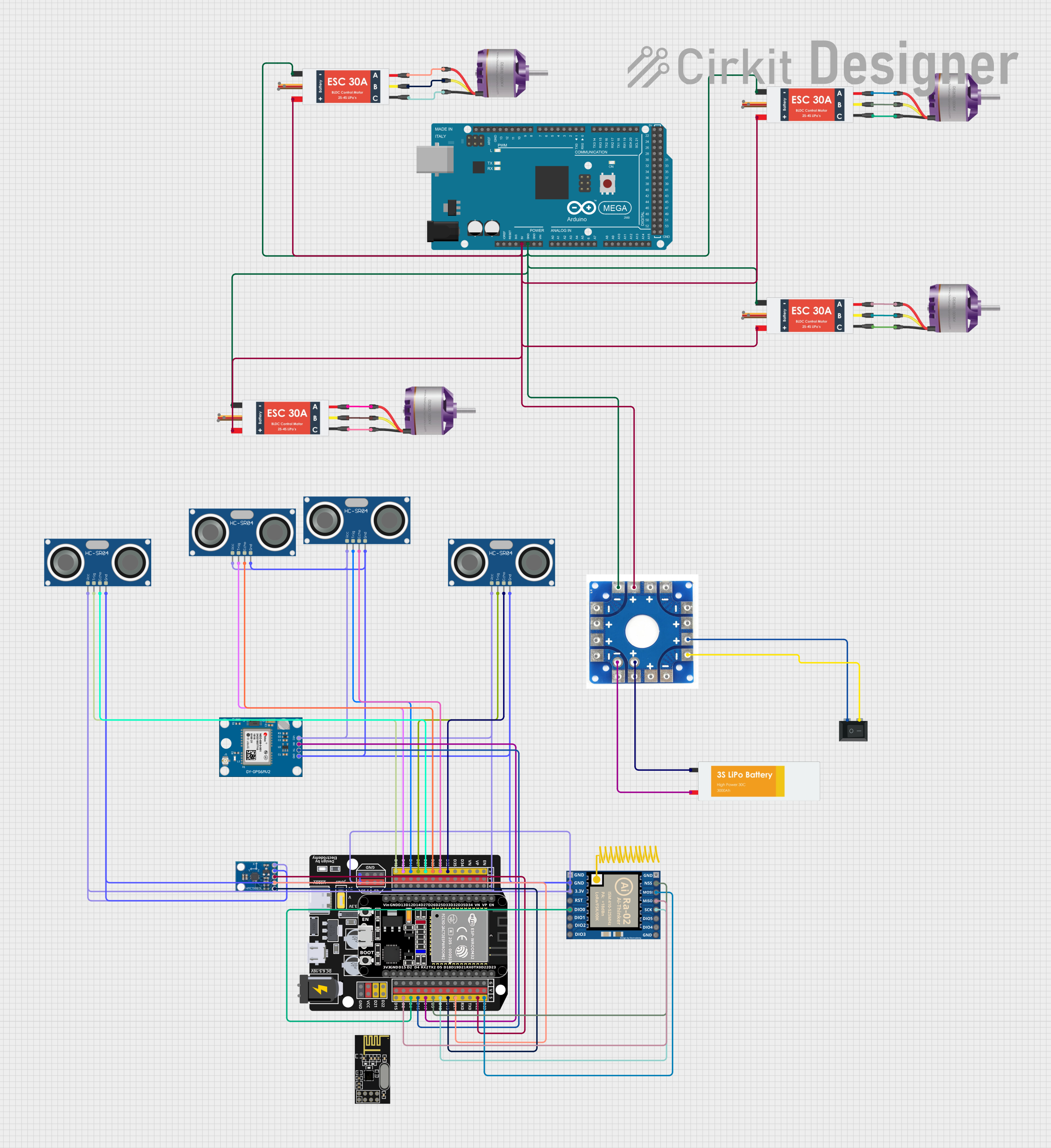
Summary
This document provides a detailed overview of a circuit designed to control brushless motors using an Arduino Mega 2560 as the main microcontroller. The circuit includes a power distribution board that distributes power from a Lipo battery to various components, including electronic speed controllers (ESCs) for motor control, sensors, and communication modules. A rocker switch is used to control the power flow. The circuit also integrates a GPS module, a compass, ultrasonic sensors for distance measurement, a radio communication module (SX1278), and an NRF24L01 module for wireless communication.
Component List
Power Distribution Board
- Distributes power from the battery to the circuit components.
Lipo Battery
- Provides the main power source for the circuit.
Rocker Switch (SPST)
- Controls the on/off state of the circuit.
Arduino Mega 2560
- Acts as the central processing unit, controlling the ESCs and communicating with sensors and modules.
Electronic Speed Controllers (ESC)
- Four ESCs are used to control the speed and direction of four brushless motors.
Brushless Motors
- Four motors that provide the mechanical power for movement.
Neo 6M GPS Module
- Provides location data to the system.
HMC5883L Compass
- A digital compass that provides heading information.
HC-SR04 Ultrasonic Sensors
- Four sensors used for distance measurement.
SX1278
- A radio communication module for long-range communication.
ESP32 - Expansion Board
- An expansion board that provides additional connectivity and interfaces for the ESP32 module.
NRF24L01
- A wireless communication module for short-range communication.
Wiring Details
Power Distribution Board
- Connected to the Lipo Battery, Rocker Switch, ESCs, and Arduino Mega 2560.
Lipo Battery
- Provides VCC and GND to the Power Distribution Board.
Rocker Switch (SPST)
- Controls the connection between the Lipo Battery and the Power Distribution Board.
Arduino Mega 2560
- GND connected to the Power Distribution Board and ESCs.
- 5V connected to the Power Distribution Board.
Electronic Speed Controllers (ESC)
- Battery VCC and GND connected to the Power Distribution Board.
- Each ESC's M1, M2, and M3 pins connected to the corresponding L1, L2, and L3 pins of a Brushless Motor.
Brushless Motors
- L1, L2, and L3 pins connected to the corresponding M1, M2, and M3 pins of an ESC.
Neo 6M GPS Module
- GND and VCC connected to the ESP32 - Expansion Board.
- TX and RX connected to the ESP32 - Expansion Board for serial communication.
HMC5883L Compass
- GND and VCC connected to the ESP32 - Expansion Board.
- DRDY, SDA, and SCL connected to the ESP32 - Expansion Board for data communication.
HC-SR04 Ultrasonic Sensors
- GND and VCC connected to the ESP32 - Expansion Board.
- TRIG and ECHO pins connected to the ESP32 - Expansion Board for triggering and echo reception.
SX1278
- GND and 3.3V connected to the ESP32 - Expansion Board.
- RST, DIO0, NSS, MOSI, MISO, and SCK connected to the ESP32 - Expansion Board for SPI communication.
ESP32 - Expansion Board
- Provides power and data connections to the Neo 6M GPS Module, HMC5883L Compass, HC-SR04 Ultrasonic Sensors, and SX1278 module.
NRF24L01
- Not detailed in the wiring list, assumed not to be connected in this circuit.
Documented Code
Arduino Mega 2560 Code (sketch.ino)
void setup() {
  // put your setup code here, to run once:

}

void loop() {
  // put your main code here, to run repeatedly:

}
Note: The provided code for the Arduino Mega 2560 is a template with empty setup and loop functions. This code should be populated with the logic required to control the ESCs, read sensor data, and communicate with other modules.
ESP32 - Expansion Board Code
No code provided for the ESP32 - Expansion Board.