
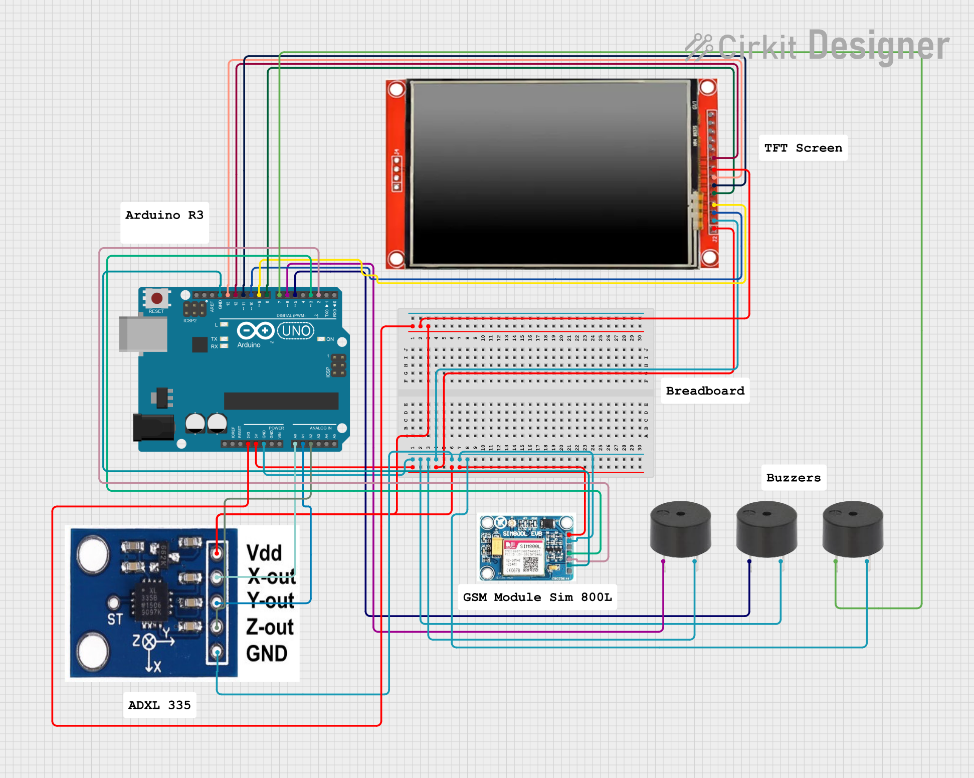
Circuit Documentation
Summary
This document provides a detailed overview of a circuit that includes an Arduino UNO microcontroller, an LCD TFT screen, multiple buzzers, an ADXXL335 accelerometer, and a SIM 800L GSM module. The document includes a component list, wiring details, and the embedded code used in the microcontroller.
Component List
Arduino UNO
- Description: A microcontroller board based on the ATmega328P.
- Pins: UNUSED, IOREF, Reset, 3.3V, 5V, GND, Vin, A0, A1, A2, A3, A4, A5, SCL, SDA, AREF, D13, D12, D11, D10, D9, D8, D7, D6, D5, D4, D3, D2, D1, D0
LCD TFT screen ILI9488 HD
- Description: A high-definition LCD TFT screen.
- Pins: PEN, TDO, TDI, VCC (3.3~5V), GND, CS, RST, D/C, SDI(MOSI), SCK, BL, SDO(MISO), TCS, TCK
Buzzer
- Description: A simple buzzer for sound output.
- Pins: PIN, GND
ADXXL335
- Description: A 3-axis accelerometer.
- Pins: VCC, X-OUT, Y-OUT, Z-OUT, GND
SIM 800L V2.0 GSM
- Description: A GSM module for communication.
- Pins: SIM_TXD, VDD, SIM.RXD, 5V/4V, GND, RST
Wiring Details
Arduino UNO
- 5V: Connected to VCC of ADXXL335, VCC (3.3~5V) of LCD TFT screen, 5V/4V of SIM 800L GSM, and 3.3V of Arduino UNO.
- GND: Connected to GND of all buzzers, GND of LCD TFT screen, GND of ADXXL335, and GND of SIM 800L GSM.
- A0: Connected to X-OUT of ADXXL335.
- A1: Connected to Y-OUT of ADXXL335.
- A2: Connected to Z-OUT of ADXXL335.
- D13: Connected to SCK of LCD TFT screen.
- D12: Connected to SDO(MISO) of LCD TFT screen.
- D11: Connected to SDI(MOSI) of LCD TFT screen.
- D10: Connected to CS of LCD TFT screen.
- D9: Connected to RST of LCD TFT screen.
- D8: Connected to D/C of LCD TFT screen.
- D7: Connected to PIN of one buzzer.
- D6: Connected to PIN of another buzzer.
- D5: Connected to PIN of another buzzer.
- D3: Connected to SIM_TXD of SIM 800L GSM.
- D2: Connected to SIM.RXD of SIM 800L GSM.
LCD TFT screen ILI9488 HD
- VCC (3.3~5V): Connected to 5V of Arduino UNO.
- GND: Connected to GND of Arduino UNO.
- SCK: Connected to D13 of Arduino UNO.
- SDO(MISO): Connected to D12 of Arduino UNO.
- SDI(MOSI): Connected to D11 of Arduino UNO.
- CS: Connected to D10 of Arduino UNO.
- RST: Connected to D9 of Arduino UNO.
- D/C: Connected to D8 of Arduino UNO.
- BL: Connected to 3.3V of Arduino UNO.
Buzzer
- PIN: Connected to D7, D6, and D5 of Arduino UNO respectively.
- GND: Connected to GND of Arduino UNO.
ADXXL335
- VCC: Connected to 5V of Arduino UNO.
- X-OUT: Connected to A0 of Arduino UNO.
- Y-OUT: Connected to A1 of Arduino UNO.
- Z-OUT: Connected to A2 of Arduino UNO.
- GND: Connected to GND of Arduino UNO.
SIM 800L V2.0 GSM
- SIM_TXD: Connected to D3 of Arduino UNO.
- SIM.RXD: Connected to D2 of Arduino UNO.
- 5V/4V: Connected to 5V of Arduino UNO.
- GND: Connected to GND of Arduino UNO.
Code Documentation
Arduino UNO Code
void setup() {
  // put your setup code here, to run once:

}

void loop() {
  // put your main code here, to run repeatedly:

}
This code is a basic template for the Arduino UNO. The setup() function is used to initialize any settings or configurations, and the loop() function contains the main code that runs repeatedly. Currently, both functions are empty and need to be filled with the appropriate logic for the specific application.