
Arduino Mega 2560-Based Automated Plant Watering System with Soil and Water Level Sensors
View and Edit Project In Cirkit Designer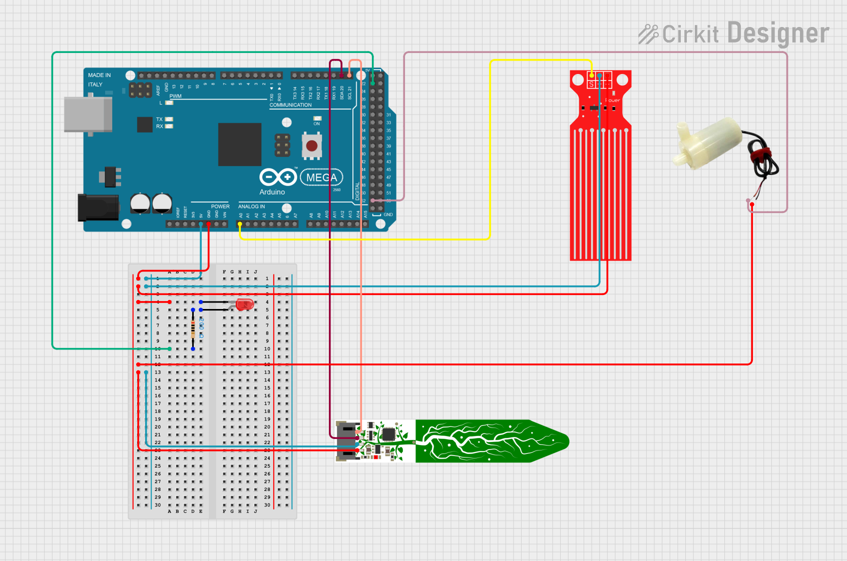
Circuit Documentation
Summary
This circuit involves an Arduino Mega 2560 microcontroller interfacing with a water level sensor, a soil moisture sensor, a 5V mini water pump, and an LED with a resistor. The circuit is designed to monitor water levels and soil moisture, and control a water pump accordingly. The LED serves as an indicator.
Component List
Arduino Mega 2560
- Description: A microcontroller board based on the ATmega2560.
- Pins: IOREF, RESET, 3V3, 5V, GND, VIN, A0-A15, D0-D53, AREF, SDA, SCL
Water Level Sensor
- Description: A sensor to detect water levels.
- Pins: SIG, VCC, GND
Adafruit STEMMA Soil Sensor
- Description: A sensor to measure soil moisture.
- Pins: GND, VIN, SDA, SCL
5V Mini Water Pump
- Description: A small water pump operating at 5V.
- Pins: Positive pin, Negative pin
LED: Two Pin (Red)
- Description: A red LED.
- Pins: Cathode, Anode
Resistor
- Description: A resistor with a resistance of 200 Ohms.
- Pins: Pin1, Pin2
Wiring Details
Arduino Mega 2560
- GND: Connected to the cathode of the LED, GND of the Water Level Sensor, negative pin of the 5V mini water pump, and GND of the Adafruit STEMMA Soil Sensor.
- D22: Connected to Pin2 of the Resistor.
- 5V: Connected to VCC of the Water Level Sensor and VIN of the Adafruit STEMMA Soil Sensor.
- A0: Connected to SIG of the Water Level Sensor.
- D21/SCL: Connected to SCL of the Adafruit STEMMA Soil Sensor.
- D20/SDA: Connected to SDA of the Adafruit STEMMA Soil Sensor.
- D52: Connected to the positive pin of the 5V mini water pump.
Water Level Sensor
- GND: Connected to GND of the Arduino Mega 2560.
- VCC: Connected to 5V of the Arduino Mega 2560.
- SIG: Connected to A0 of the Arduino Mega 2560.
Adafruit STEMMA Soil Sensor
- GND: Connected to GND of the Arduino Mega 2560.
- VIN: Connected to 5V of the Arduino Mega 2560.
- SDA: Connected to D20/SDA of the Arduino Mega 2560.
- SCL: Connected to D21/SCL of the Arduino Mega 2560.
5V Mini Water Pump
- Negative pin: Connected to GND of the Arduino Mega 2560.
- Positive pin: Connected to D52 of the Arduino Mega 2560.
LED: Two Pin (Red)
- Cathode: Connected to GND of the Arduino Mega 2560.
- Anode: Connected to Pin1 of the Resistor.
Resistor
- Pin1: Connected to the anode of the LED.
- Pin2: Connected to D22 of the Arduino Mega 2560.
Documented Code
Arduino Mega 2560 Code
void setup() {
  // put your setup code here, to run once:

}

void loop() {
  // put your main code here, to run repeatedly:

}
This code is a basic template for the Arduino Mega 2560. The setup function is used to initialize any settings or configurations, and the loop function contains the main logic that runs repeatedly. You can add your specific logic for controlling the water pump, reading sensor values, and driving the LED in these functions.